


You also want an ePaper? Increase the reach of your titles
YUMPU automatically turns print PDFs into web optimized ePapers that Google loves.
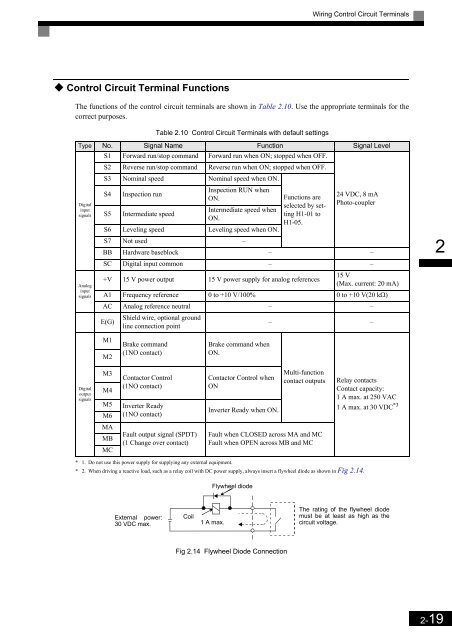
Wiring Control Circuit Terminals<br />
Control Circuit Terminal Functions<br />
The functions of the control circuit terminals are shown in Table 2.10. Use the appropriate terminals for the<br />
correct purposes.<br />
Table 2.10 Control Circuit Terminals with default settings<br />
Type No. Signal Name Function Signal Level<br />
S1 Forward run/stop command Forward run when ON; stopped when OFF.<br />
Digital<br />
input<br />
signals<br />
Analog<br />
input<br />
signals<br />
S2 Reverse run/stop command Reverse run when ON; stopped when OFF.<br />
S3 Nominal speed Nominal speed when ON.<br />
S4<br />
Inspection run<br />
Inspection RUN when<br />
ON.<br />
S5 Intermediate speed<br />
Intermediate speed when<br />
ON.<br />
S6 Leveling speed Leveling speed when ON.<br />
S7 Not used –<br />
Functions are<br />
selected by setting<br />
H1-01 to<br />
H1-05.<br />
24 VDC, 8 mA<br />
Photo-coupler<br />
BB Hardware baseblock – –<br />
SC Digital input common – –<br />
+V 15 V power output 15 V power supply for analog references<br />
15 V<br />
(Max. current: 20 mA)<br />
A1 Frequency reference 0 to +10 V/100% 0 to +10 V(20 kΩ)<br />
AC Analog reference neutral – –<br />
E(G)<br />
Shield wire, optional ground<br />
line connection point<br />
– –<br />
2<br />
M1<br />
M2<br />
Brake command<br />
(1NO contact)<br />
Brake command when<br />
ON.<br />
Digital<br />
output<br />
signals<br />
M3<br />
M4<br />
M5<br />
M6<br />
Contactor Control<br />
(1NO contact)<br />
Inverter Ready<br />
(1NO contact)<br />
Contactor Control when<br />
ON<br />
Inverter Ready when ON.<br />
Multi-function<br />
contact outputs<br />
Relay contacts<br />
Contact capacity:<br />
1 A max. at 250 VAC<br />
1 A max. at 30 VDC *3<br />
MA<br />
MB<br />
MC<br />
Fault output signal (SPDT)<br />
(1 Change over contact)<br />
Fault when CLOSED across MA and MC<br />
Fault when OPEN across MB and MC<br />
* 1. Do not use this power supply for supplying any external equipment.<br />
* 2. When driving a reactive load, such as a relay coil with DC power supply, always insert a flywheel diode as shown in Fig 2.14.<br />
Flywheel diode<br />
External power:<br />
30 VDC max.<br />
Coil<br />
1 A max.<br />
The rating of the flywheel diode<br />
must be at least as high as the<br />
circuit voltage.<br />
Fig 2.14 Flywheel Diode Connection<br />
2-19


