


Create successful ePaper yourself
Turn your PDF publications into a flip-book with our unique Google optimized e-Paper software.
Protective Functions<br />
•Setting Motor Protection Operation Time (L1-02)<br />
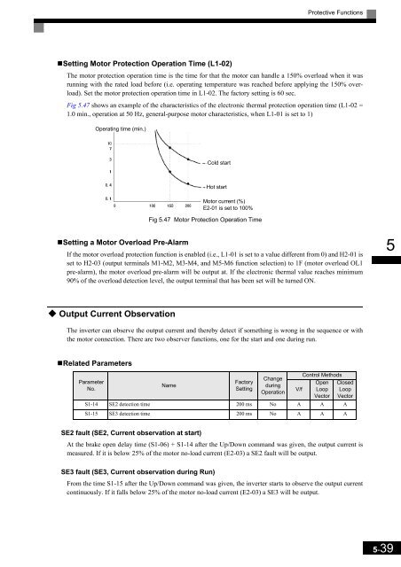
The motor protection operation time is the time for that the motor can handle a 150% overload when it was<br />
running with the rated load before (i.e. operating temperature was reached before applying the 150% overload).<br />
Set the motor protection operation time in L1-02. The factory setting is 60 sec.<br />
Fig 5.47 shows an example of the characteristics of the electronic thermal protection operation time (L1-02 =<br />
1.0 min., operation at 50 Hz, general-purpose motor characteristics, when L1-01 is set to 1)<br />
Operating time (min.)<br />
Cold start<br />
Hot start<br />
Motor current (%)<br />
E2-01 is set to 100%<br />
Fig 5.47 Motor Protection Operation Time<br />
•Setting a Motor Overload Pre-Alarm<br />
If the motor overload protection function is enabled (i.e., L1-01 is set to a value different from 0) and H2-01 is<br />
set to H2-03 (output terminals M1-M2, M3-M4, and M5-M6 function selection) to 1F (motor overload OL1<br />
pre-alarm), the motor overload pre-alarm will be output at. If the electronic thermal value reaches minimum<br />
90% of the overload detection level, the output terminal that has been set will be turned ON.<br />
5<br />
Output Current Observation<br />
The inverter can observe the output current and thereby detect if something is wrong in the sequence or with<br />
the motor connection. There are two observer functions, one for the start and one during run.<br />
•Related Parameters<br />
Parameter<br />
No.<br />
Name<br />
Factory<br />
Setting<br />
Change<br />
during<br />
Operation<br />
V/f<br />
Control Methods<br />
Open Closed<br />
Loop Loop<br />
Vector Vector<br />
S1-14 SE2 detection time 200 ms No A A A<br />
S1-15 SE3 detection time 200 ms No A A A<br />
SE2 fault (SE2, Current observation at start)<br />
At the brake open delay time (S1-06) + S1-14 after the Up/Down command was given, the output current is<br />
measured. If it is below 25% of the motor no-load current (E2-03) a SE2 fault will be output.<br />
SE3 fault (SE3, Current observation during Run)<br />
From the time S1-15 after the Up/Down command was given, the inverter starts to observe the output current<br />
continuously. If it falls below 25% of the motor no-load current (E2-03) a SE3 will be output.<br />
5-39


