


Create successful ePaper yourself
Turn your PDF publications into a flip-book with our unique Google optimized e-Paper software.
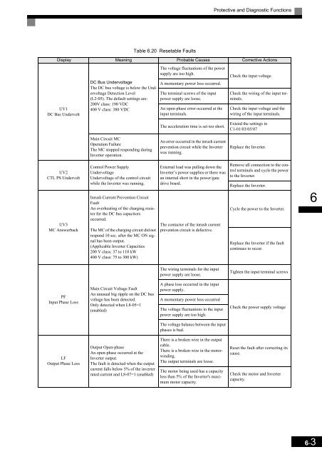
Protective and Diagnostic Functions<br />
Table 6.20 Resetable Faults<br />
Display Meaning Probable Causes Corrective Actions<br />
UV1<br />
DC Bus Undervolt<br />
DC Bus Undervoltage<br />
The DC bus voltage is below the Undervoltage<br />
Detection Level<br />
(L2-05). The default settings are:<br />
200V class: 190 VDC<br />
400 V class: 380 VDC<br />
The voltage fluctuations of the power<br />
supply are too high.<br />
A momentary power loss occurred.<br />
The terminal screws of the input<br />
power supply are loose.<br />
An open-phase error occurred at the<br />
input terminals.<br />
The acceleration time is set too short.<br />
Check the input voltage.<br />
Check the wiring of the input terminals.<br />
Check the input voltage and the<br />
wiring of the input terminals.<br />
Extend the settings in<br />
C1-01/03/05/07<br />
Main Circuit MC<br />
Operation Failure<br />
The MC stopped responding during<br />
Inverter operation.<br />
An error occurred in the inrush current<br />
prevention circuit while the Inverter<br />
was running.<br />
Replace the Inverter.<br />
UV2<br />
CTL PS Undervolt<br />
UV3<br />
MC Answerback<br />
Control Power Supply<br />
Undervoltage<br />
Undervoltage of the control circuit<br />
while the Inverter was running.<br />
Inrush Current Prevention Circuit<br />
Fault<br />
An overheating of the charging resistor<br />
for the DC bus capacitors<br />
occurred.<br />
The MC of the charging circuit did not<br />
respond 10 sec. after the MC ON signal<br />
has been output.<br />
(Applicable Inverter Capacities<br />
200 V class: 37 to 110 kW<br />
400 V class: 75 to 300 kW)<br />
External load was pulling down the<br />
Inverter’s power supplies or there was<br />
an internal short in the power/gate<br />
drive board.<br />
The contactor of the inrush current<br />
prevention circuit is defective.<br />
Remove all connection to the control<br />
terminals and cycle the power<br />
to the Inverter.<br />
Replace the Inverter.<br />
Cycle the power to the Inverter.<br />
Replace the Inverter if the fault<br />
continues to occur.<br />
6<br />
The wiring terminals for the input<br />
power supply are loose.<br />
Tighten the input terminal screws<br />
PF<br />
Input Phase Loss<br />
Main Circuit Voltage Fault<br />
An unusual big ripple on the DC bus<br />
voltage has been detected.<br />
Only detected when L8-05=1<br />
(enabled)<br />
A phase loss occurred in the input<br />
power supply.<br />
A momentary power loss occurred<br />
The voltage fluctuations in the input<br />
power supply are too high.<br />
Check the power supply voltage<br />
The voltage balance between the input<br />
phases is bad.<br />
LF<br />
Output Phase Loss<br />
Output Open-phase<br />
An open-phase occurred at the<br />
Inverter output.<br />
The fault is detected when the output<br />
current falls below 5% of the inverter<br />
rated current and L8-07=1 (enabled)<br />
There is a broken wire in the output<br />
cable.<br />
There is a broken wire in the motorwinding.<br />
The output terminals are loose.<br />
The motor being used has a capacity<br />
less than 5% of the Inverter's maximum<br />
motor capacity.<br />
Reset the fault after correcting its<br />
cause.<br />
Check the motor and Inverter<br />
capacity.<br />
6-3


