


You also want an ePaper? Increase the reach of your titles
YUMPU automatically turns print PDFs into web optimized ePapers that Google loves.
Table 3.17 Key Functions (Continued)<br />
Key Name Function<br />
JOG Key<br />
Enables jog operation when the Inverter is operated from the Digital<br />
Operator.<br />
FWD/REV Key<br />
Selects the rotation direction of the motor when the Inverter is operated<br />
from the Digital Operator.<br />
Shift/RESET Key<br />
Increment Key<br />
Decrement Key<br />
DATA/ENTER Key<br />
Sets the active digit when programming parameters.<br />
Also acts as the Reset key when a fault has occurred.<br />
Selects menu items, sets parameter numbers, and increments set values.<br />
Used to move to the next item or data.<br />
Selects menu items, sets parameter numbers, and decrements set values.<br />
Used to move to the previous item or data.<br />
Pressed to enter menu items, parameters, and set values.<br />
Also used to switch from one screen to another.<br />
RUN Key<br />
STOP Key<br />
Starts the Inverter operation when the Inverter is being controlled by<br />
the Digital Operator.<br />
Stops Inverter operation.<br />
This key can be enabled or disabled when operating from the control<br />
circuit terminal by setting parameter o2-02.<br />
Note: Except in diagrams, Keys are referred to the key names listed in the above table.<br />
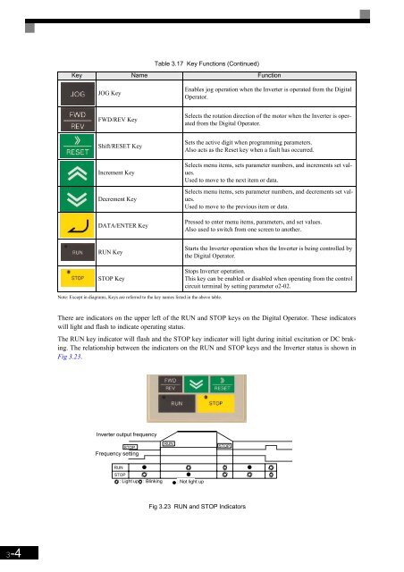
There are indicators on the upper left of the RUN and STOP keys on the Digital Operator. These indicators<br />
will light and flash to indicate operating status.<br />
The RUN key indicator will flash and the STOP key indicator will light during initial excitation or DC braking.<br />
The relationship between the indicators on the RUN and STOP keys and the Inverter status is shown in<br />
Fig 3.23.<br />
Inverter output frequency<br />
Frequency setting<br />
: Light up : Blinking : Not light up<br />
Fig 3.23 RUN and STOP Indicators<br />
3-4


