


You also want an ePaper? Increase the reach of your titles
YUMPU automatically turns print PDFs into web optimized ePapers that Google loves.
Inverter<br />
Forward<br />
command<br />
Motor<br />
PG (encoder)<br />
Pulse output<br />
A-phase leads when set value = 0 B-phase leads when set value = 1<br />
A-phase<br />
B-phase<br />
A-phase<br />
B-phase<br />
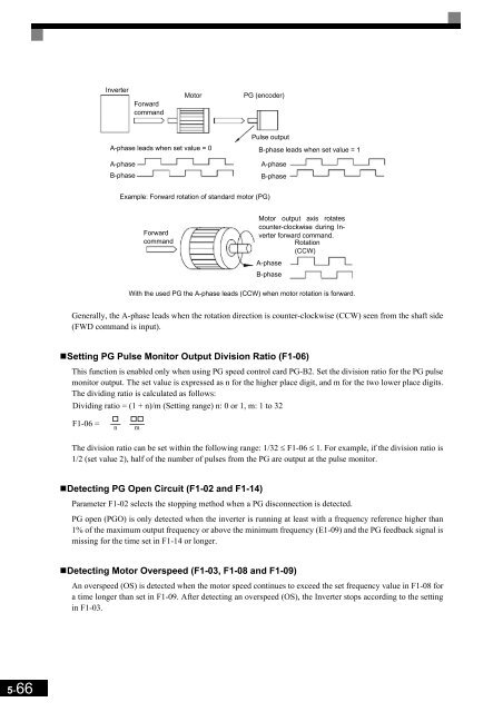
Example: Forward rotation of standard motor (PG)<br />
Forward<br />
command<br />
Motor output axis rotates<br />
counter-clockwise during Inverter<br />
forward command.<br />
Rotation<br />
(CCW)<br />
A-phase<br />
B-phase<br />
With the used PG the A-phase leads (CCW) when motor rotation is forward.<br />
Generally, the A-phase leads when the rotation direction is counter-clockwise (CCW) seen from the shaft side<br />
(FWD command is input).<br />
•Setting PG Pulse Monitor Output Division Ratio (F1-06)<br />
This function is enabled only when using PG speed control card PG-B2. Set the division ratio for the PG pulse<br />
monitor output. The set value is expressed as n for the higher place digit, and m for the two lower place digits.<br />
The dividing ratio is calculated as follows:<br />
Dividing ratio = (1 + n)/m (Setting range) n: 0 or 1, m: 1 to 32<br />
F1-06 =<br />
<br />
n<br />
<br />
m<br />
The division ratio can be set within the following range: 1/32 ≤ F1-06 ≤ 1. For example, if the division ratio is<br />
1/2 (set value 2), half of the number of pulses from the PG are output at the pulse monitor.<br />
•Detecting PG Open Circuit (F1-02 and F1-14)<br />
Parameter F1-02 selects the stopping method when a PG disconnection is detected.<br />
PG open (PGO) is only detected when the inverter is running at least with a frequency reference higher than<br />
1% of the maximum output frequency or above the minimum frequency (E1-09) and the PG feedback signal is<br />
missing for the time set in F1-14 or longer.<br />
•Detecting Motor Overspeed (F1-03, F1-08 and F1-09)<br />
An overspeed (OS) is detected when the motor speed continues to exceed the set frequency value in F1-08 for<br />
a time longer than set in F1-09. After detecting an overspeed (OS), the Inverter stops according to the setting<br />
in F1-03.<br />
5-66


