


You also want an ePaper? Increase the reach of your titles
YUMPU automatically turns print PDFs into web optimized ePapers that Google loves.
PG Option Cards<br />
PG Option Cards<br />
To get a more precise speed control the inverter can be equipped with a PG option card to connect a pulse generator.<br />
Two different PG cards can be used, the PG-B2 and the PG-X2. Refer to page 2-24, Option Card Models<br />
and Specifications to see details.<br />
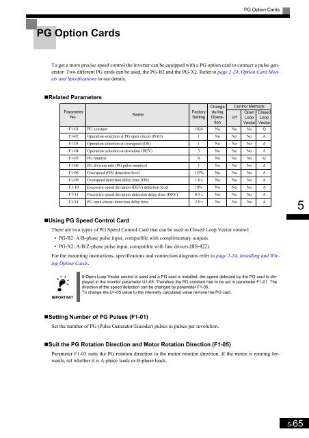
•Related Parameters<br />
Parameter<br />
No.<br />
Name<br />
Factory<br />
Setting<br />
Change<br />
during<br />
Operation<br />
Control Methods<br />
V/f<br />
Open<br />
Loop<br />
Vector<br />
F1-01 PG constant 1024 No No No Q<br />
F1-02 Operation selection at PG open circuit (PGO) 1 No No No A<br />
F1-03 Operation selection at overspeed (OS) 1 No No No A<br />
F1-04 Operation selection at deviation (DEV) 3 No No No A<br />
F1-05 PG rotation 0 No No No Q<br />
F1-06 PG division rate (PG pulse monitor) 1 No No No A<br />
F1-08 Overspeed (OS) detection level 115% No No No A<br />
F1-09 Overspeed detection delay time (OS) 1.0 s No No No A<br />
F1-10 Excessive speed deviation (DEV) detection level 10% No No No A<br />
Closed<br />
Loop<br />
Vector<br />
F1-11 Excessive speed deviation detection delay time (DEV) 0.5 s No No No A<br />
F1-14 PG open-circuit detection delay time 2.0 s No No No A<br />
5<br />
•Using PG Speed Control Card<br />
There are two types of PG Speed Control Card that can be used in Closed Loop Vector control:<br />
• PG-B2: A/B-phase pulse input, compatible with complimentary outputs.<br />
• PG-X2: A/B/Z-phase pulse input, compatible with line drivers (RS-422).<br />
For the mounting instructions, specifications and connection diagrams refer to page 2-24, Installing and Wiring<br />
Option Cards.<br />
IMPORTANT<br />
If Open Loop Vector control is used and a PG card is installed, the speed detected by the PG card is displayed<br />
in the monitor parameter U1-05. Therefore the PG constant has to be set in parameter F1-01. The<br />
direction of the speed detection can be changed by parameter F1-05.<br />
To change the U1-05 value to the internally calculated value remove the PG card.<br />
•Setting Number of PG Pulses (F1-01)<br />
Set the number of PG (Pulse Generator/Encoder) pulses in pulses per revolution.<br />
•Suit the PG Rotation Direction and Motor Rotation Direction (F1-05)<br />
Parameter F1-05 suits the PG rotation direction to the motor rotation direction. If the motor is rotating forwards,<br />
set whether it is A-phase leads or B-phase leads.<br />
5-65


