


Create successful ePaper yourself
Turn your PDF publications into a flip-book with our unique Google optimized e-Paper software.
•Wiring the Output Side of Main Circuit<br />
Observe the following precautions when wiring the main output circuits.<br />
Connecting the Inverter and Motor<br />
Connect output terminals U/T1, V/T2, and W/T3 respective to the motor lead wires U, V, and W.<br />
Check that the motor rotates forward with the forward run command. Switch over any two of the output terminals<br />
to each other and reconnect if the motor rotates in reverse with the forward run command.<br />
Never Connect a Power Supply to Output Terminals<br />
Never connect a power supply to output terminals U/T1, V/T2, and W/T3. If voltage is applied to the output<br />
terminals, the internal circuits of the Inverter will be damaged.<br />
Never Short or Ground Output Terminals<br />
If the output terminals are touched with bare hands or the output wires come into contact with the Inverter<br />
case, an electric shock or grounding may occur. This is extremely hazardous. Do not short the output wires.<br />
Do Not Use a Phase Advancing Capacitor<br />
Never connect a phase advancing capacitor to an output circuit. The high-frequency components of the<br />
Inverter output may overheat and be damaged and may cause other parts to burn.<br />
Using a Magnetic Contactor<br />
Check the control sequence to make sure, that the magnetic contactor (MC) between the Inverter and motor is<br />
not turned ON or OFF during inverter operation. If the MC is turned ON while the Inverter is operating, a<br />
large inrush current will be created and the inverter’s overcurrent protection may operate.<br />
Cable Length between Inverter and Motor<br />
The cable between the Inverter and motor is 30 m max.<br />
•Ground Wiring<br />
Observe the following precautions when wiring the ground line.<br />
• Always use the ground terminal of the 200 V Inverter with a ground resistance of less than 100 Ω and that<br />
of the 400 V Inverter with a ground resistance of less than 10 Ω.<br />
• Do not share the ground wire with other devices, such as welding machines or power tools.<br />
• Always use a ground wire that complies with technical standards on electrical equipment and minimize the<br />
length of the ground wire.<br />
Leakage current flows through the Inverter. Therefore, if the distance between the ground electrode and<br />
the ground terminal is too long, potential on the ground terminal of the Inverter will become unstable.<br />
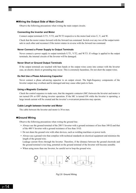
• When using more than one Inverter, be careful not to loop the ground wire.<br />
OK<br />
NO<br />
Fig 2.8 Ground Wiring<br />
2-14


