- Page 1 and 2: Contents Warnings .................
- Page 3 and 4: Terminal Function Parameters: H....
- Page 5 and 6: If the Motor Overheats.............
- Page 7 and 8: Warnings CAUTION Cables must not be
- Page 9 and 10: • 5. Electrical Connection Carry
- Page 11 and 12: Ground clip Ground plate The ground
- Page 13 and 14: • Installation inverters and EMC
- Page 15 and 16: Handling Inverters 1 This chapter d
- Page 17 and 18: Confirmations upon Delivery Confirm
- Page 19 and 20: Confirmations upon Delivery Compon
- Page 21 and 22: Exterior and Mounting Dimensions Ex
- Page 23 and 24: Installation Orientation and Space
- Page 25 and 26: Removing/Attaching the Digital Oper
- Page 27 and 28: Removing/Attaching the Digital Oper
- Page 29 and 30: Wiring 2 This chapter describes wir
- Page 31 and 32: Connection Diagram Circuit Descrip
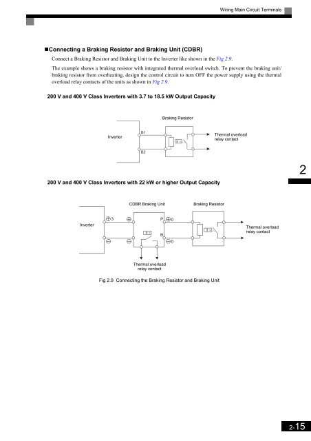
- Page 33 and 34: Wiring Main Circuit Terminals Wirin
- Page 35 and 36: Wiring Main Circuit Terminals Inver
- Page 37 and 38: Wiring Main Circuit Terminals Main
- Page 39 and 40: Wiring Main Circuit Terminals Stan
- Page 41: Wiring Main Circuit Terminals Insta
- Page 45 and 46: Wiring Control Circuit Terminals Wi
- Page 47 and 48: Wiring Control Circuit Terminals C
- Page 49 and 50: Wiring Control Circuit Terminals C
- Page 51 and 52: Wiring Check Wiring Check Checks C
- Page 53 and 54: Installing and Wiring Option Cards
- Page 55 and 56: Installing and Wiring Option Cards
- Page 57 and 58: Installing and Wiring Option Cards
- Page 59 and 60: Digital Monitor/ Operator and Modes
- Page 61 and 62: Digital Operator JVOP-160 Digital O
- Page 63 and 64: Digital Operator JVOP-160 Inverter
- Page 65 and 66: Digital Operator JVOP-160 Drive Mo
- Page 67 and 68: Digital Operator JVOP-160 Advanced
- Page 69 and 70: Digital Operator JVOP-160 Verify M
- Page 71 and 72: User Parameters This chapter descri
- Page 73 and 74: Digital Operation Display Functions
- Page 75 and 76: Digital Operation Display Functions
- Page 77 and 78: User Parameter Tables User Paramete
- Page 79 and 80: User Parameter Tables Application
- Page 81 and 82: User Parameter Tables Tuning Param
- Page 83 and 84: User Parameter Tables •Motor Slip
- Page 85 and 86: User Parameter Tables •Speed Cont
- Page 87 and 88: User Parameter Tables Parameter Num
- Page 89 and 90: User Parameter Tables Parameter Num
- Page 91 and 92: User Parameter Tables Parameter Num
- Page 93 and 94:
User Parameter Tables •Digital Ou
- Page 95 and 96:
User Parameter Tables Terminal Fun
- Page 97 and 98:
User Parameter Tables Setting Value
- Page 99 and 100:
User Parameter Tables Constant Numb
- Page 101 and 102:
User Parameter Tables •Stall Prev
- Page 103 and 104:
User Parameter Tables •Torque Det
- Page 105 and 106:
User Parameter Tables Parameter Num
- Page 107 and 108:
User Parameter Tables •Feed Forwa
- Page 109 and 110:
User Parameter Tables Parameter Num
- Page 111 and 112:
User Parameter Tables Parameter Num
- Page 113 and 114:
User Parameter Tables •S2 Slip Co
- Page 115 and 116:
User Parameter Tables U: Monitor P
- Page 117 and 118:
User Parameter Tables Parameter Num
- Page 119 and 120:
User Parameter Tables • Fault Tra
- Page 121 and 122:
User Parameter Tables Factory Sett
- Page 123 and 124:
User Parameter Tables Factory Sett
- Page 125 and 126:
Parameter Settings by Function 5 Ca
- Page 127 and 128:
Carrier Frequency Derating and Curr
- Page 129 and 130:
Control Sequence Speed Reference S
- Page 131 and 132:
Control Sequence •Separate Speed
- Page 133 and 134:
Control Sequence The following spee
- Page 135 and 136:
Control Sequence The inspection run
- Page 137 and 138:
Control Sequence The timing chart a
- Page 139 and 140:
Control Sequence Timing t8-t9 t9-t1
- Page 141 and 142:
Acceleration and Deceleration Chara
- Page 143 and 144:
Acceleration and Deceleration Chara
- Page 145 and 146:
Acceleration and Deceleration Chara
- Page 147 and 148:
Speed Detection and Speed Limitatio
- Page 149 and 150:
Speed Detection and Speed Limitatio
- Page 151 and 152:
Improving the Operation Performance
- Page 153 and 154:
Improving the Operation Performance
- Page 155 and 156:
Improving the Operation Performance
- Page 157 and 158:
Improving the Operation Performance
- Page 159 and 160:
Protective Functions •Related Par
- Page 161 and 162:
Protective Functions Limiting Moto
- Page 163 and 164:
Protective Functions •Setting Mot
- Page 165 and 166:
Inverter Protection Output Open Ph
- Page 167 and 168:
Input Terminal Functions Input Term
- Page 169 and 170:
Input Terminal Functions •Multi-f
- Page 171 and 172:
Output Terminal Functions Output Te
- Page 173 and 174:
Output Terminal Functions •During
- Page 175 and 176:
Motor and V/f Pattern Setup the lin
- Page 177 and 178:
Motor and V/f Pattern Setup After t
- Page 179 and 180:
Motor and V/f Pattern Setup Settin
- Page 181 and 182:
Digital Operator/Monitor Functions
- Page 183 and 184:
Digital Operator/Monitor Functions
- Page 185 and 186:
Digital Operator/Monitor Functions
- Page 187 and 188:
Digital Operator/Monitor Functions
- Page 189 and 190:
PG Option Cards PG Option Cards To
- Page 191 and 192:
PG Option Cards •Detecting Speed
- Page 193 and 194:
Battery Operation •Battery sequen
- Page 195 and 196:
Automatic Fault Restart Automatic F
- Page 197 and 198:
Troubleshooting This chapter descri
- Page 199 and 200:
Protective and Diagnostic Functions
- Page 201 and 202:
Protective and Diagnostic Functions
- Page 203 and 204:
Protective and Diagnostic Functions
- Page 205 and 206:
Protective and Diagnostic Functions
- Page 207 and 208:
Protective and Diagnostic Functions
- Page 209 and 210:
Protective and Diagnostic Functions
- Page 211 and 212:
Troubleshooting Troubleshooting Due
- Page 213 and 214:
Troubleshooting If Motor Decelerat
- Page 215 and 216:
Troubleshooting If There is Mechan
- Page 217 and 218:
Maintenance and Inspection This cha
- Page 219 and 220:
Maintenance and Inspection Periodi
- Page 221 and 222:
Maintenance and Inspection •200 V
- Page 223 and 224:
Specifications This chapter describ
- Page 225 and 226:
Standard Inverter Specifications
- Page 227 and 228:
Standard Inverter Specifications Ta
- Page 229 and 230:
Appendix This chapter provides prec
- Page 231 and 232:
Inverter Application Precautions
- Page 233 and 234:
User Constants User Constants Facto
- Page 235 and 236:
User Constants Table 9.7 User Const
- Page 237 and 238:
User Constants Table 9.7 User Const
- Page 239 and 240:
User Constants Table 9.7 User Const