- Page 1 and 2:
Handbook of Photovoltaic Science an
- Page 3 and 4:
We dedicate this book to all those
- Page 5 and 6:
xxiv LIST OF CONTRIBUTORS Phone: +1
- Page 7 and 8:
xxvi LIST OF CONTRIBUTORS 28040 Mad
- Page 9 and 10:
Contents List of Contributors xxiii
- Page 11 and 12:
CONTENTS ix 4.3.1 The Balance Equat
- Page 13 and 14:
CONTENTS xi 7.4 Manufacturing Proce
- Page 15 and 16:
CONTENTS xiii 9.8 Future-generation
- Page 17 and 18:
CONTENTS xv 12.1.2 Designs for Amor
- Page 19 and 20:
CONTENTS xvii 14.3.3 CdS/CdTe Inter
- Page 21 and 22:
CONTENTS xix 18.2.2 Batteries with
- Page 23 and 24:
CONTENTS xxi 22.2 PV in Architectur
- Page 25 and 26:
1 Status, Trends, Challenges and th
- Page 27 and 28:
WHAT IS PHOTOVOLTAICS? 3 1.2 WHAT I
- Page 29 and 30:
SIX MYTHS OF PHOTOVOLTAICS 5 Sunlig
- Page 31 and 32:
SIX MYTHS OF PHOTOVOLTAICS 7 of 10
- Page 33 and 34:
SIX MYTHS OF PHOTOVOLTAICS 9 2500 W
- Page 35 and 36:
HISTORY OF PHOTOVOLTAICS 11 the maj
- Page 37 and 38:
HISTORY OF PHOTOVOLTAICS 13 the USA
- Page 39 and 40:
PV COSTS, MARKETS AND FORECASTS 15
- Page 41 and 42:
PV COSTS, MARKETS AND FORECASTS 17
- Page 43 and 44:
GOALS OF PV RESEARCH AND MANUFACTUR
- Page 45 and 46:
GLOBAL TRENDS IN PERFORMANCE AND AP
- Page 47 and 48:
CRYSTALLINE SILICON PROGRESS AND CH
- Page 49 and 50:
CRYSTALLINE SILICON PROGRESS AND CH
- Page 51 and 52:
THIN FILM PROGRESS AND CHALLENGES 2
- Page 53 and 54:
THIN FILM PROGRESS AND CHALLENGES 2
- Page 55 and 56:
CONCENTRATION PV SYSTEMS 31 reality
- Page 57 and 58:
BALANCE OF SYSTEMS 33 Percentage of
- Page 59 and 60:
BALANCE OF SYSTEMS 35 Total capital
- Page 61 and 62:
FUTURE OF EMERGING PV TECHNOLOGIES
- Page 63 and 64:
CONCLUSIONS 39 Yet, in all these al
- Page 65 and 66:
REFERENCES 41 the other hand, hybri
- Page 67 and 68:
REFERENCES 43 69. Mickelson R, Chen
- Page 69 and 70:
46 MOTIVATION FOR PV APPLICATION AN
- Page 71 and 72:
48 MOTIVATION FOR PV APPLICATION AN
- Page 73 and 74:
50 MOTIVATION FOR PV APPLICATION AN
- Page 75 and 76:
52 MOTIVATION FOR PV APPLICATION AN
- Page 77 and 78:
54 MOTIVATION FOR PV APPLICATION AN
- Page 79 and 80:
56 MOTIVATION FOR PV APPLICATION AN
- Page 81 and 82:
58 MOTIVATION FOR PV APPLICATION AN
- Page 83 and 84:
60 MOTIVATION FOR PV APPLICATION AN
- Page 85 and 86:
62 THE PHYSICS OF THE SOLAR CELL Su
- Page 87 and 88:
64 THE PHYSICS OF THE SOLAR CELL 3.
- Page 89 and 90:
66 THE PHYSICS OF THE SOLAR CELL E
- Page 91 and 92:
68 THE PHYSICS OF THE SOLAR CELL 1.
- Page 93 and 94:
70 THE PHYSICS OF THE SOLAR CELL E
- Page 95 and 96:
72 THE PHYSICS OF THE SOLAR CELL an
- Page 97 and 98:
74 THE PHYSICS OF THE SOLAR CELL pr
- Page 99 and 100:
76 THE PHYSICS OF THE SOLAR CELL No
- Page 101 and 102:
78 THE PHYSICS OF THE SOLAR CELL E
- Page 103 and 104:
80 THE PHYSICS OF THE SOLAR CELL El
- Page 105 and 106:
82 THE PHYSICS OF THE SOLAR CELL wh
- Page 107 and 108:
84 THE PHYSICS OF THE SOLAR CELL n
- Page 109 and 110:
86 THE PHYSICS OF THE SOLAR CELL Th
- Page 111 and 112:
88 THE PHYSICS OF THE SOLAR CELL Th
- Page 113 and 114:
90 THE PHYSICS OF THE SOLAR CELL an
- Page 115 and 116:
92 THE PHYSICS OF THE SOLAR CELL an
- Page 117 and 118:
94 THE PHYSICS OF THE SOLAR CELL Ta
- Page 119 and 120:
96 THE PHYSICS OF THE SOLAR CELL cu
- Page 121 and 122:
98 THE PHYSICS OF THE SOLAR CELL 0.
- Page 123 and 124:
100 THE PHYSICS OF THE SOLAR CELL 5
- Page 125 and 126:
102 THE PHYSICS OF THE SOLAR CELL I
- Page 127 and 128:
104 THE PHYSICS OF THE SOLAR CELL 4
- Page 129 and 130:
106 THE PHYSICS OF THE SOLAR CELL T
- Page 131 and 132:
108 THE PHYSICS OF THE SOLAR CELL S
- Page 133 and 134:
110 THE PHYSICS OF THE SOLAR CELL E
- Page 135 and 136:
112 THE PHYSICS OF THE SOLAR CELL 1
- Page 137 and 138:
114 THEORETICAL LIMITS OF PHOTOVOLT
- Page 139 and 140:
116 THEORETICAL LIMITS OF PHOTOVOLT
- Page 141 and 142:
118 THEORETICAL LIMITS OF PHOTOVOLT
- Page 143 and 144:
120 THEORETICAL LIMITS OF PHOTOVOLT
- Page 145 and 146:
122 THEORETICAL LIMITS OF PHOTOVOLT
- Page 147 and 148:
124 THEORETICAL LIMITS OF PHOTOVOLT
- Page 149 and 150:
126 THEORETICAL LIMITS OF PHOTOVOLT
- Page 151 and 152:
128 THEORETICAL LIMITS OF PHOTOVOLT
- Page 153 and 154:
130 THEORETICAL LIMITS OF PHOTOVOLT
- Page 155 and 156:
132 THEORETICAL LIMITS OF PHOTOVOLT
- Page 157 and 158:
134 THEORETICAL LIMITS OF PHOTOVOLT
- Page 159 and 160:
136 THEORETICAL LIMITS OF PHOTOVOLT
- Page 161 and 162:
138 THEORETICAL LIMITS OF PHOTOVOLT
- Page 163 and 164:
140 THEORETICAL LIMITS OF PHOTOVOLT
- Page 165 and 166:
142 THEORETICAL LIMITS OF PHOTOVOLT
- Page 167 and 168:
144 THEORETICAL LIMITS OF PHOTOVOLT
- Page 169 and 170:
146 THEORETICAL LIMITS OF PHOTOVOLT
- Page 171 and 172:
148 THEORETICAL LIMITS OF PHOTOVOLT
- Page 173 and 174:
150 THEORETICAL LIMITS OF PHOTOVOLT
- Page 175 and 176:
5 Solar Grade Silicon Feedstock Bru
- Page 177 and 178:
SILICON 155 faces of silicon are (1
- Page 179 and 180:
SILICON 157 powder in the presence
- Page 181 and 182:
SILICON 159 5.2.4.1.2 Wrought alloy
- Page 183 and 184:
PRODUCTION OF METALLURGICAL GRADE S
- Page 185 and 186:
PRODUCTION OF METALLURGICAL GRADE S
- Page 187 and 188:
PRODUCTION OF METALLURGICAL GRADE S
- Page 189 and 190:
PRODUCTION OF SEMICONDUCTOR GRADE S
- Page 191 and 192:
PRODUCTION OF SEMICONDUCTOR GRADE S
- Page 193 and 194:
PRODUCTION OF SEMICONDUCTOR GRADE S
- Page 195 and 196:
PRODUCTION OF SEMICONDUCTOR GRADE S
- Page 197 and 198:
CURRENT SILICON FEEDSTOCK TO SOLAR
- Page 199 and 200:
CURRENT SILICON FEEDSTOCK TO SOLAR
- Page 201 and 202:
REQUIREMENTS OF SILICON FOR CRYSTAL
- Page 203 and 204:
REQUIREMENTS OF SILICON FOR CRYSTAL
- Page 205 and 206:
REQUIREMENTS OF SILICON FOR CRYSTAL
- Page 207 and 208:
REQUIREMENTS OF SILICON FOR CRYSTAL
- Page 209 and 210:
REQUIREMENTS OF SILICON FOR CRYSTAL
- Page 211 and 212:
REQUIREMENTS OF SILICON FOR CRYSTAL
- Page 213 and 214:
REQUIREMENTS OF SILICON FOR CRYSTAL
- Page 215 and 216:
ROUTES TO SOLAR GRADE SILICON 193 c
- Page 217 and 218:
ROUTES TO SOLAR GRADE SILICON 195 c
- Page 219 and 220:
ROUTES TO SOLAR GRADE SILICON 197 d
- Page 221 and 222:
ROUTES TO SOLAR GRADE SILICON 199 d
- Page 223 and 224:
CONCLUSIONS 201 2. Another German c
- Page 225 and 226:
REFERENCES 203 34. Fischler S, J. A
- Page 227 and 228:
6 Bulk Crystal Growth and Wafering
- Page 229 and 230:
BULK MONOCRYSTALLINE MATERIAL 207 b
- Page 231 and 232:
BULK MONOCRYSTALLINE MATERIAL 209 (
- Page 233 and 234:
BULK MONOCRYSTALLINE MATERIAL 211 O
- Page 235 and 236:
BULK MONOCRYSTALLINE MATERIAL 213 8
- Page 237 and 238:
BULK MULTICRYSTALLINE SILICON 215 I
- Page 239 and 240:
BULK MULTICRYSTALLINE SILICON 217 1
- Page 241 and 242:
BULK MULTICRYSTALLINE SILICON 219 b
- Page 243 and 244:
BULK MULTICRYSTALLINE SILICON 221 L
- Page 245 and 246:
WAFERING 223 This in turn verifies
- Page 247 and 248:
WAFERING 225 suspension of hard gri
- Page 249 and 250:
WAFERING 227 tips, they can exert v
- Page 251 and 252:
WAFERING 229 6.4.3 Wafer Quality an
- Page 253 and 254:
SILICON RIBBON AND FOIL PRODUCTION
- Page 255 and 256:
SILICON RIBBON AND FOIL PRODUCTION
- Page 257 and 258:
SILICON RIBBON AND FOIL PRODUCTION
- Page 259 and 260:
SILICON RIBBON AND FOIL PRODUCTION
- Page 261 and 262:
SILICON RIBBON AND FOIL PRODUCTION
- Page 263 and 264:
SILICON RIBBON AND FOIL PRODUCTION
- Page 265 and 266:
SILICON RIBBON AND FOIL PRODUCTION
- Page 267 and 268:
NUMERICAL SIMULATIONS OF CRYSTAL GR
- Page 269 and 270:
NUMERICAL SIMULATIONS OF CRYSTAL GR
- Page 271 and 272:
NUMERICAL SIMULATIONS OF CRYSTAL GR
- Page 273 and 274:
CONCLUSIONS 251 the supercooling de
- Page 275 and 276:
REFERENCES 253 28. Sahoo R et al.,
- Page 277 and 278:
7 Crystalline Silicon Solar Cells a
- Page 279 and 280:
CRYSTALLINE SILICON AS A PHOTOVOLTA
- Page 281 and 282:
CRYSTALLINE SILICON SOLAR CELLS 259
- Page 283 and 284:
CRYSTALLINE SILICON SOLAR CELLS 261
- Page 285 and 286:
CRYSTALLINE SILICON SOLAR CELLS 263
- Page 287 and 288:
CRYSTALLINE SILICON SOLAR CELLS 265
- Page 289 and 290:
CRYSTALLINE SILICON SOLAR CELLS 267
- Page 291 and 292:
CRYSTALLINE SILICON SOLAR CELLS 269
- Page 293 and 294:
MANUFACTURING PROCESS 271 The most
- Page 295 and 296:
MANUFACTURING PROCESS 273 3. Textur
- Page 297 and 298:
MANUFACTURING PROCESS 275 materials
- Page 299 and 300:
MANUFACTURING PROCESS 277 nearly 50
- Page 301 and 302:
MANUFACTURING PROCESS 279 Figure 7.
- Page 303 and 304:
VARIATIONS TO THE BASIC PROCESS 281
- Page 305 and 306:
MULTICRYSTALLINE CELLS 283 of defec
- Page 307 and 308:
MULTICRYSTALLINE CELLS 285 better s
- Page 309 and 310:
MULTICRYSTALLINE CELLS 287 Figure 7
- Page 311 and 312:
OTHER INDUSTRIAL APPROACHES 289 TCO
- Page 313 and 314:
CRYSTALLINE SILICON PHOTOVOLTAIC MO
- Page 315 and 316:
CRYSTALLINE SILICON PHOTOVOLTAIC MO
- Page 317 and 318:
ELECTRICAL AND OPTICAL PERFORMANCE
- Page 319 and 320:
ELECTRICAL AND OPTICAL PERFORMANCE
- Page 321 and 322:
ELECTRICAL AND OPTICAL PERFORMANCE
- Page 323 and 324:
FIELD PERFORMANCE OF MODULES 301 7.
- Page 325 and 326:
REFERENCES 303 REFERENCES 1. Luque
- Page 327 and 328:
REFERENCES 305 75. Lenkeit B et al.
- Page 329 and 330:
8 Thin-film Silicon Solar Cells Bhu
- Page 331 and 332:
INTRODUCTION 309 Open circuit volta
- Page 333 and 334:
A REVIEW OF CURRENT THIN-FILM SI CE
- Page 335 and 336:
A REVIEW OF CURRENT THIN-FILM SI CE
- Page 337 and 338:
A REVIEW OF CURRENT THIN-FILM SI CE
- Page 339 and 340:
A REVIEW OF CURRENT THIN-FILM SI CE
- Page 342:
CVD Excimer laser crystallization U
- Page 345 and 346:
A REVIEW OF CURRENT THIN-FILM SI CE
- Page 347 and 348:
n-type silicon (0.2 µm) p-type sil
- Page 349 and 350:
DESIGN CONCEPTS OF TF-SI SOLAR CELL
- Page 351 and 352:
DESIGN CONCEPTS OF TF-SI SOLAR CELL
- Page 353 and 354:
DESIGN CONCEPTS OF TF-SI SOLAR CELL
- Page 355 and 356:
DESIGN CONCEPTS OF TF-SI SOLAR CELL
- Page 357 and 358:
DESIGN CONCEPTS OF TF-SI SOLAR CELL
- Page 359 and 360:
DESIGN CONCEPTS OF TF-SI SOLAR CELL
- Page 361 and 362:
DESIGN CONCEPTS OF TF-SI SOLAR CELL
- Page 363 and 364:
DESIGN CONCEPTS OF TF-SI SOLAR CELL
- Page 365 and 366:
DESIGN CONCEPTS OF TF-SI SOLAR CELL
- Page 367 and 368:
DESIGN CONCEPTS OF TF-SI SOLAR CELL
- Page 369 and 370:
DESIGN CONCEPTS OF TF-SI SOLAR CELL
- Page 371 and 372:
DESIGN CONCEPTS OF TF-SI SOLAR CELL
- Page 373 and 374:
DESIGN CONCEPTS OF TF-SI SOLAR CELL
- Page 375 and 376:
DESIGN CONCEPTS OF TF-SI SOLAR CELL
- Page 377 and 378:
CONCLUSION 353 Introduction of H af
- Page 379 and 380:
REFERENCES 355 17. Kamins T, Ed, Po
- Page 381 and 382:
REFERENCES 357 98. Symko M, Sopori
- Page 383 and 384:
360 HIGH-EFFICIENCY III-V MULTIJUNC
- Page 385 and 386:
362 HIGH-EFFICIENCY III-V MULTIJUNC
- Page 387 and 388:
364 HIGH-EFFICIENCY III-V MULTIJUNC
- Page 389 and 390:
366 HIGH-EFFICIENCY III-V MULTIJUNC
- Page 391 and 392:
368 HIGH-EFFICIENCY III-V MULTIJUNC
- Page 393 and 394:
370 HIGH-EFFICIENCY III-V MULTIJUNC
- Page 395 and 396:
372 HIGH-EFFICIENCY III-V MULTIJUNC
- Page 397 and 398:
374 HIGH-EFFICIENCY III-V MULTIJUNC
- Page 399 and 400:
376 HIGH-EFFICIENCY III-V MULTIJUNC
- Page 401 and 402:
378 HIGH-EFFICIENCY III-V MULTIJUNC
- Page 403 and 404:
380 HIGH-EFFICIENCY III-V MULTIJUNC
- Page 405 and 406:
382 HIGH-EFFICIENCY III-V MULTIJUNC
- Page 407 and 408:
384 HIGH-EFFICIENCY III-V MULTIJUNC
- Page 409 and 410:
386 HIGH-EFFICIENCY III-V MULTIJUNC
- Page 411 and 412:
388 HIGH-EFFICIENCY III-V MULTIJUNC
- Page 413 and 414:
390 HIGH-EFFICIENCY III-V MULTIJUNC
- Page 415 and 416:
392 HIGH-EFFICIENCY III-V MULTIJUNC
- Page 417 and 418:
394 HIGH-EFFICIENCY III-V MULTIJUNC
- Page 419 and 420:
396 HIGH-EFFICIENCY III-V MULTIJUNC
- Page 421 and 422:
398 HIGH-EFFICIENCY III-V MULTIJUNC
- Page 423 and 424:
400 HIGH-EFFICIENCY III-V MULTIJUNC
- Page 425 and 426:
402 HIGH-EFFICIENCY III-V MULTIJUNC
- Page 427 and 428:
404 HIGH-EFFICIENCY III-V MULTIJUNC
- Page 429 and 430:
406 HIGH-EFFICIENCY III-V MULTIJUNC
- Page 431 and 432:
408 HIGH-EFFICIENCY III-V MULTIJUNC
- Page 433 and 434:
410 HIGH-EFFICIENCY III-V MULTIJUNC
- Page 435 and 436:
10 Space Solar Cells and Arrays She
- Page 437 and 438:
THE HISTORY OF SPACE SOLAR CELLS 41
- Page 439 and 440:
THE CHALLENGE FOR SPACE SOLAR CELLS
- Page 441 and 442:
THE CHALLENGE FOR SPACE SOLAR CELLS
- Page 443 and 444:
THE CHALLENGE FOR SPACE SOLAR CELLS
- Page 445 and 446:
THE CHALLENGE FOR SPACE SOLAR CELLS
- Page 447 and 448:
SILICON SOLAR CELLS 425 Figure 10.7
- Page 449 and 450:
III-V SOLAR CELLS 427 n+-GaAs n-AlI
- Page 451 and 452:
III-V SOLAR CELLS 429 missions with
- Page 453 and 454:
SPACE SOLAR ARRAYS 431 supported af
- Page 455 and 456:
SPACE SOLAR ARRAYS 433 JPL-25888AC
- Page 457 and 458:
SPACE SOLAR ARRAYS 435 Figure 10.13
- Page 459 and 460:
SPACE SOLAR ARRAYS 437 Figure 10.15
- Page 461 and 462:
SPACE SOLAR ARRAYS 439 0.31 Astrono
- Page 463 and 464:
FUTURE CELL AND ARRAY POSSIBILITIES
- Page 465 and 466:
FUTURE CELL AND ARRAY POSSIBILITIES
- Page 467 and 468:
POWER SYSTEM FIGURES OF MERIT 445 A
- Page 469 and 470:
REFERENCES 447 8. Statler R, Curtin
- Page 471 and 472:
11 Photovoltaic Concentrators Richa
- Page 473 and 474:
INTRODUCTION 451 markets most often
- Page 475 and 476:
BASIC TYPES OF CONCENTRATORS 453 ha
- Page 477 and 478:
BASIC TYPES OF CONCENTRATORS 455 is
- Page 479 and 480:
BASIC TYPES OF CONCENTRATORS 457 sk
- Page 481 and 482:
BASIC TYPES OF CONCENTRATORS 459 Ho
- Page 483 and 484:
HISTORICAL OVERVIEW 461 thereafter.
- Page 485 and 486:
HISTORICAL OVERVIEW 463 Figure 11.6
- Page 487 and 488: HISTORICAL OVERVIEW 465 production
- Page 489 and 490: HISTORICAL OVERVIEW 467 Figure 11.1
- Page 491 and 492: HISTORICAL OVERVIEW 469 n + bussbar
- Page 493 and 494: HISTORICAL OVERVIEW 471 array [33].
- Page 495 and 496: HISTORICAL OVERVIEW 473 Solar radia
- Page 497 and 498: OPTICS OF CONCENTRATORS 475 q max,
- Page 499 and 500: OPTICS OF CONCENTRATORS 477 If r 1
- Page 501 and 502: OPTICS OF CONCENTRATORS 479 r i Med
- Page 503 and 504: OPTICS OF CONCENTRATORS 481 When θ
- Page 505 and 506: OPTICS OF CONCENTRATORS 483 filled
- Page 507 and 508: OPTICS OF CONCENTRATORS 485 q i q i
- Page 509 and 510: OPTICS OF CONCENTRATORS 487 For lar
- Page 511 and 512: OPTICS OF CONCENTRATORS 489 on a co
- Page 513 and 514: OPTICS OF CONCENTRATORS 491 gleaned
- Page 515 and 516: OPTICS OF CONCENTRATORS 493 Solar c
- Page 517 and 518: CURRENT CONCENTRATOR ACTIVITIES 495
- Page 519 and 520: CURRENT CONCENTRATOR ACTIVITIES 497
- Page 521 and 522: CURRENT CONCENTRATOR ACTIVITIES 499
- Page 523 and 524: REFERENCES 501 11. Boes E, “Photo
- Page 525 and 526: REFERENCES 503 60. Uematsu T et al.
- Page 527 and 528: 506 AMORPHOUS SILICON-BASED SOLAR C
- Page 529 and 530: 508 AMORPHOUS SILICON-BASED SOLAR C
- Page 531 and 532: 510 AMORPHOUS SILICON-BASED SOLAR C
- Page 533 and 534: 512 AMORPHOUS SILICON-BASED SOLAR C
- Page 535 and 536: 514 AMORPHOUS SILICON-BASED SOLAR C
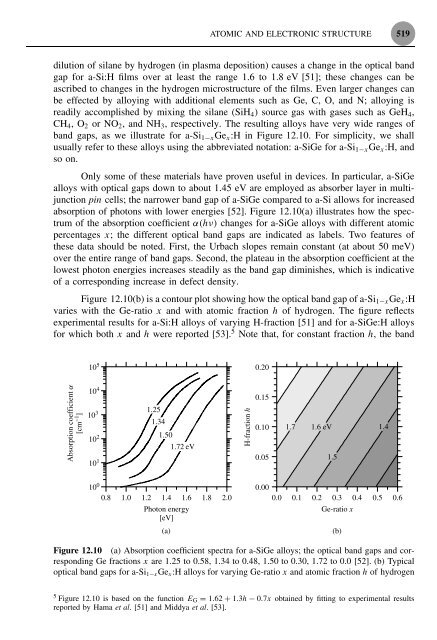
- Page 537: 516 AMORPHOUS SILICON-BASED SOLAR C
- Page 541 and 542: 520 AMORPHOUS SILICON-BASED SOLAR C
- Page 543 and 544: 522 AMORPHOUS SILICON-BASED SOLAR C
- Page 545 and 546: 524 AMORPHOUS SILICON-BASED SOLAR C
- Page 547 and 548: 526 AMORPHOUS SILICON-BASED SOLAR C
- Page 549 and 550: 528 AMORPHOUS SILICON-BASED SOLAR C
- Page 551 and 552: 530 AMORPHOUS SILICON-BASED SOLAR C
- Page 553 and 554: 532 AMORPHOUS SILICON-BASED SOLAR C
- Page 555 and 556: 534 AMORPHOUS SILICON-BASED SOLAR C
- Page 557 and 558: 536 AMORPHOUS SILICON-BASED SOLAR C
- Page 559 and 560: 538 AMORPHOUS SILICON-BASED SOLAR C
- Page 561 and 562: 540 AMORPHOUS SILICON-BASED SOLAR C
- Page 563 and 564: 542 AMORPHOUS SILICON-BASED SOLAR C
- Page 565 and 566: 544 AMORPHOUS SILICON-BASED SOLAR C
- Page 567 and 568: 546 AMORPHOUS SILICON-BASED SOLAR C
- Page 569 and 570: 548 AMORPHOUS SILICON-BASED SOLAR C
- Page 571 and 572: 550 AMORPHOUS SILICON-BASED SOLAR C
- Page 573 and 574: 552 AMORPHOUS SILICON-BASED SOLAR C
- Page 575 and 576: 554 AMORPHOUS SILICON-BASED SOLAR C
- Page 577 and 578: 556 AMORPHOUS SILICON-BASED SOLAR C
- Page 579 and 580: 558 AMORPHOUS SILICON-BASED SOLAR C
- Page 581 and 582: 560 AMORPHOUS SILICON-BASED SOLAR C
- Page 583 and 584: 562 AMORPHOUS SILICON-BASED SOLAR C
- Page 585 and 586: 564 AMORPHOUS SILICON-BASED SOLAR C
- Page 587 and 588: 13 Cu(InGa)Se 2 Solar Cells William
- Page 589 and 590:
INTRODUCTION 569 CdS. The latter en
- Page 591 and 592:
MATERIAL PROPERTIES 571 Even though
- Page 593 and 594:
MATERIAL PROPERTIES 573 800 d 785 T
- Page 595 and 596:
MATERIAL PROPERTIES 575 3.2 x = 0.2
- Page 597 and 598:
MATERIAL PROPERTIES 577 1µm Figure
- Page 599 and 600:
DEPOSITION METHODS 579 though other
- Page 601 and 602:
DEPOSITION METHODS 581 much higher
- Page 603 and 604:
DEPOSITION METHODS 583 in the tempe
- Page 605 and 606:
JUNCTION AND DEVICE FORMATION 585 f
- Page 607 and 608:
JUNCTION AND DEVICE FORMATION 587 0
- Page 609 and 610:
JUNCTION AND DEVICE FORMATION 589 T
- Page 611 and 612:
JUNCTION AND DEVICE FORMATION 591 d
- Page 613 and 614:
DEVICE OPERATION 593 the voltage. F
- Page 615 and 616:
DEVICE OPERATION 595 1.0 0.8 500 80
- Page 617 and 618:
DEVICE OPERATION 597 1.4 V OC [Volt
- Page 619 and 620:
DEVICE OPERATION 599 13.5.3 The Cu(
- Page 621 and 622:
DEVICE OPERATION 601 Table 13.5 Hig
- Page 623 and 624:
MANUFACTURING ISSUES 603 can well f
- Page 625 and 626:
MANUFACTURING ISSUES 605 P1 P1 Mo G
- Page 627 and 628:
MANUFACTURING ISSUES 607 Finally, f
- Page 629 and 630:
THE Cu(InGa)Se 2 OUTLOOK 609 active
- Page 631 and 632:
REFERENCES 611 With all these chall
- Page 633 and 634:
REFERENCES 613 81. Stolt L, Hedstr
- Page 635 and 636:
REFERENCES 615 168. Fahrenbruch A,
- Page 637 and 638:
14 Cadmium Telluride Solar Cells Br
- Page 639 and 640:
INTRODUCTION 619 In contrast to p/n
- Page 641 and 642:
CdTe PROPERTIES AND THIN-FILM FABRI
- Page 643 and 644:
CdTe PROPERTIES AND THIN-FILM FABRI
- Page 645 and 646:
CdTe PROPERTIES AND THIN-FILM FABRI
- Page 647 and 648:
CdTe PROPERTIES AND THIN-FILM FABRI
- Page 649 and 650:
CdTe PROPERTIES AND THIN-FILM FABRI
- Page 651 and 652:
CdTe THIN-FILM SOLAR CELLS 631 orie
- Page 653 and 654:
CdTe THIN-FILM SOLAR CELLS 633 14.3
- Page 655 and 656:
CdTe THIN-FILM SOLAR CELLS 635 CdTe
- Page 657 and 658:
CdTe THIN-FILM SOLAR CELLS 637 CdTe
- Page 659 and 660:
CdTe THIN-FILM SOLAR CELLS 639 800
- Page 661 and 662:
CdTe THIN-FILM SOLAR CELLS 641 10
- Page 663 and 664:
CdTe THIN-FILM SOLAR CELLS 643 CdTe
- Page 665 and 666:
CdTe THIN-FILM SOLAR CELLS 645 forw
- Page 667 and 668:
CdTe THIN-FILM SOLAR CELLS 647 30 R
- Page 669 and 670:
CdTe THIN-FILM SOLAR CELLS 649 The
- Page 671 and 672:
CdTe MODULES 651 14.4 CdTe MODULES
- Page 673 and 674:
THE FUTURE OF CdTe-BASED SOLAR CELL
- Page 675 and 676:
THE FUTURE OF CdTe-BASED SOLAR CELL
- Page 677 and 678:
REFERENCES 657 This chapter has sho
- Page 679 and 680:
REFERENCES 659 60. Wei S, Mtg. Reco
- Page 681 and 682:
REFERENCES 661 152. McCandless B, Q
- Page 683 and 684:
15 Dye-sensitized Solar Cells Kohji
- Page 685 and 686:
INTRODUCTION TO DYE-SENSITIZED SOLA
- Page 687 and 688:
INTRODUCTION TO DYE-SENSITIZED SOLA
- Page 689 and 690:
INTRODUCTION TO DYE-SENSITIZED SOLA
- Page 691 and 692:
INTRODUCTION TO DYE-SENSITIZED SOLA
- Page 693 and 694:
INTRODUCTION TO DYE-SENSITIZED SOLA
- Page 695 and 696:
INTRODUCTION TO DYE-SENSITIZED SOLA
- Page 697 and 698:
INTRODUCTION TO DYE-SENSITIZED SOLA
- Page 699 and 700:
DSSC FABRICATION (η = 8%) 679 alko
- Page 701 and 702:
DSSC FABRICATION (η = 8%) 681 15.2
- Page 703 and 704:
NEW DEVELOPMENTS 683 of highly effi
- Page 706 and 707:
NEW DEVELOPMENTS 685 HOOC COOH HOOC
- Page 708 and 709:
NEW DEVELOPMENTS 687 photosensitize
- Page 710 and 711:
NEW DEVELOPMENTS 689 of these ionic
- Page 712 and 713:
APPROACH TO COMMERCIALIZATION 691 1
- Page 714:
Institute and reference Table 15.3
- Page 717 and 718:
SUMMARY AND PROSPECTS 695 Chemicals
- Page 719 and 720:
REFERENCES 697 4. Dare-Edwards M et
- Page 721 and 722:
REFERENCES 699 96. Tennakone K, Kum
- Page 723 and 724:
16 Measurement and Characterization
- Page 725 and 726:
RATING PV PERFORMANCE 703 Spectral
- Page 727:
λ [nm] Table 16.3 AM0 standard sol
- Page 731:
171.5 7.01E − 1 372.5 1074 573.5
- Page 735:
228.5 52.940 429.5 1501 630.7 1682
- Page 739:
288.5 328.400 489.5 1994 689.1 1506
- Page 742 and 743:
RATING PV PERFORMANCE 713 The extra
- Page 744 and 745:
RATING PV PERFORMANCE 715 of about
- Page 746 and 747:
RATING PV PERFORMANCE 717 Energy [W
- Page 748 and 749:
RATING PV PERFORMANCE 719 16.2.4 Tr
- Page 750 and 751:
CURRENT VERSUS VOLTAGE MEASUREMENTS
- Page 752 and 753:
CURRENT VERSUS VOLTAGE MEASUREMENTS
- Page 754 and 755:
CURRENT VERSUS VOLTAGE MEASUREMENTS
- Page 756 and 757:
CURRENT VERSUS VOLTAGE MEASUREMENTS
- Page 758 and 759:
CURRENT VERSUS VOLTAGE MEASUREMENTS
- Page 760 and 761:
CURRENT VERSUS VOLTAGE MEASUREMENTS
- Page 762 and 763:
CURRENT VERSUS VOLTAGE MEASUREMENTS
- Page 764 and 765:
CURRENT VERSUS VOLTAGE MEASUREMENTS
- Page 766 and 767:
CURRENT VERSUS VOLTAGE MEASUREMENTS
- Page 768 and 769:
SPECTRAL RESPONSIVITY MEASUREMENTS
- Page 770 and 771:
SPECTRAL RESPONSIVITY MEASUREMENTS
- Page 772 and 773:
SPECTRAL RESPONSIVITY MEASUREMENTS
- Page 774 and 775:
MODULE QUALIFICATION AND CERTIFICAT
- Page 776 and 777:
REFERENCES 747 REFERENCES 1. Emery
- Page 778 and 779:
REFERENCES 749 62. Standard IEC 608
- Page 780 and 781:
REFERENCES 751 130. Dondero R, Zirk
- Page 782 and 783:
17 Photovoltaic Systems Klaus Preis
- Page 784 and 785:
PV POWER SYSTEM CONFIGURATION AND A
- Page 786 and 787:
PV POWER SYSTEM CONFIGURATION AND A
- Page 788 and 789:
PV POWER SYSTEM CONFIGURATION AND A
- Page 790 and 791:
PV POWER SYSTEM CONFIGURATION AND A
- Page 792 and 793:
PV POWER SYSTEM CONFIGURATION AND A
- Page 794 and 795:
PV POWER SYSTEM CONFIGURATION AND A
- Page 796 and 797:
PV POWER SYSTEM CONFIGURATION AND A
- Page 798 and 799:
PV POWER SYSTEM CONFIGURATION AND A
- Page 800 and 801:
PV POWER SYSTEM CONFIGURATION AND A
- Page 802 and 803:
PV POWER SYSTEM CONFIGURATION AND A
- Page 804 and 805:
PV POWER SYSTEM CONFIGURATION AND A
- Page 806 and 807:
PV POWER SYSTEM CONFIGURATION AND A
- Page 808 and 809:
PV POWER SYSTEM CONFIGURATION AND A
- Page 810 and 811:
PV POWER SYSTEM CONFIGURATION AND A
- Page 812 and 813:
PV POWER SYSTEM CONFIGURATION AND A
- Page 814 and 815:
COMPONENTS FOR PV SYSTEMS 785 NASA
- Page 816 and 817:
COMPONENTS FOR PV SYSTEMS 787 volta
- Page 818 and 819:
COMPONENTS FOR PV SYSTEMS 789 well
- Page 820 and 821:
COMPONENTS FOR PV SYSTEMS 791 A sig
- Page 822 and 823:
COMPONENTS FOR PV SYSTEMS 793 In st
- Page 824 and 825:
FUTURE DEVELOPMENTS IN PHOTOVOLTAIC
- Page 826 and 827:
REFERENCES 797 CL Controllable load
- Page 828 and 829:
18 Electrochemical Storage for Phot
- Page 830 and 831:
GENERAL CONCEPT OF ELECTROCHEMICAL
- Page 832 and 833:
GENERAL CONCEPT OF ELECTROCHEMICAL
- Page 834 and 835:
GENERAL CONCEPT OF ELECTROCHEMICAL
- Page 836 and 837:
GENERAL CONCEPT OF ELECTROCHEMICAL
- Page 838 and 839:
GENERAL CONCEPT OF ELECTROCHEMICAL
- Page 840 and 841:
GENERAL CONCEPT OF ELECTROCHEMICAL
- Page 842 and 843:
TYPICAL OPERATION CONDITIONS OF BAT
- Page 844 and 845:
TYPICAL OPERATION CONDITIONS OF BAT
- Page 846 and 847:
SECONDARY ELECTROCHEMICAL ACCUMULAT
- Page 848:
Table 18.4 Overview of the technica
- Page 851 and 852:
SECONDARY ELECTROCHEMICAL ACCUMULAT
- Page 853 and 854:
SECONDARY ELECTROCHEMICAL ACCUMULAT
- Page 855 and 856:
SECONDARY ELECTROCHEMICAL ACCUMULAT
- Page 857 and 858:
SECONDARY ELECTROCHEMICAL ACCUMULAT
- Page 859 and 860:
SECONDARY ELECTROCHEMICAL ACCUMULAT
- Page 861 and 862:
SECONDARY ELECTROCHEMICAL ACCUMULAT
- Page 863 and 864:
SECONDARY ELECTROCHEMICAL ACCUMULAT
- Page 865 and 866:
SECONDARY ELECTROCHEMICAL ACCUMULAT
- Page 867 and 868:
SECONDARY ELECTROCHEMICAL ACCUMULAT
- Page 869 and 870:
SECONDARY ELECTROCHEMICAL ACCUMULAT
- Page 871 and 872:
SECONDARY ELECTROCHEMICAL ACCUMULAT
- Page 873 and 874:
SECONDARY ELECTROCHEMICAL ACCUMULAT
- Page 875 and 876:
SECONDARY ELECTROCHEMICAL ACCUMULAT
- Page 877 and 878:
SECONDARY ELECTROCHEMICAL ACCUMULAT
- Page 879 and 880:
BATTERY SYSTEMS WITH EXTERNAL STORA
- Page 881 and 882:
BATTERY SYSTEMS WITH EXTERNAL STORA
- Page 883 and 884:
BATTERY SYSTEMS WITH EXTERNAL STORA
- Page 885 and 886:
BATTERY SYSTEMS WITH EXTERNAL STORA
- Page 887 and 888:
INVESTMENT AND LIFETIME COST CONSID
- Page 889 and 890:
CONCLUSION 859 This example is just
- Page 891 and 892:
REFERENCES 861 10. Ruddell A et al.
- Page 893 and 894:
19 Power Conditioning for Photovolt
- Page 895 and 896:
CONTROLLERS AND MONITORING SYSTEMS
- Page 897 and 898:
CONTROLLERS AND MONITORING SYSTEMS
- Page 899 and 900:
CONTROLLERS AND MONITORING SYSTEMS
- Page 901 and 902:
CONTROLLERS AND MONITORING SYSTEMS
- Page 903 and 904:
CONTROLLERS AND MONITORING SYSTEMS
- Page 905 and 906:
CONTROLLERS AND MONITORING SYSTEMS
- Page 907 and 908:
CONTROLLERS AND MONITORING SYSTEMS
- Page 909 and 910:
CONTROLLERS AND MONITORING SYSTEMS
- Page 911 and 912:
INVERTERS 881 19.2 INVERTERS 19.2.1
- Page 913 and 914:
INVERTERS 883 Current [A] MPP Power
- Page 915 and 916:
INVERTERS 885 S1 S3 DC source AC ou
- Page 917 and 918:
INVERTERS 887 V PV V load t 0 t 1 t
- Page 919 and 920:
INVERTERS 889 The resulting voltage
- Page 921 and 922:
INVERTERS 891 12 V 24 V 48 V 96 V 1
- Page 923 and 924:
INVERTERS 893 U DC voltage level U
- Page 925 and 926:
INVERTERS 895 100 55 Hz 50 Hz Frequ
- Page 927 and 928:
INVERTERS 897 S1 L C 1 C 2 AC outpu
- Page 929 and 930:
INVERTERS 899 Time delay Seconds Mi
- Page 931 and 932:
INVERTERS 901 Separated part of the
- Page 933 and 934:
REFERENCES 903 5. Gonzalez G, Hill
- Page 935 and 936:
906 ENERGY COLLECTED AND DELIVERED
- Page 937 and 938:
908 ENERGY COLLECTED AND DELIVERED
- Page 939 and 940:
910 ENERGY COLLECTED AND DELIVERED
- Page 941 and 942:
912 ENERGY COLLECTED AND DELIVERED
- Page 943 and 944:
914 ENERGY COLLECTED AND DELIVERED
- Page 945 and 946:
916 ENERGY COLLECTED AND DELIVERED
- Page 947 and 948:
918 ENERGY COLLECTED AND DELIVERED
- Page 949 and 950:
920 ENERGY COLLECTED AND DELIVERED
- Page 951 and 952:
922 ENERGY COLLECTED AND DELIVERED
- Page 953 and 954:
924 ENERGY COLLECTED AND DELIVERED
- Page 955 and 956:
926 ENERGY COLLECTED AND DELIVERED
- Page 957 and 958:
928 ENERGY COLLECTED AND DELIVERED
- Page 959 and 960:
930 ENERGY COLLECTED AND DELIVERED
- Page 961 and 962:
932 ENERGY COLLECTED AND DELIVERED
- Page 963 and 964:
934 ENERGY COLLECTED AND DELIVERED
- Page 965 and 966:
936 ENERGY COLLECTED AND DELIVERED
- Page 967 and 968:
938 ENERGY COLLECTED AND DELIVERED
- Page 969 and 970:
940 ENERGY COLLECTED AND DELIVERED
- Page 971 and 972:
942 ENERGY COLLECTED AND DELIVERED
- Page 973 and 974:
944 ENERGY COLLECTED AND DELIVERED
- Page 975 and 976:
946 ENERGY COLLECTED AND DELIVERED
- Page 977 and 978:
948 ENERGY COLLECTED AND DELIVERED
- Page 979 and 980:
950 ENERGY COLLECTED AND DELIVERED
- Page 981 and 982:
952 ENERGY COLLECTED AND DELIVERED
- Page 983 and 984:
954 ENERGY COLLECTED AND DELIVERED
- Page 985 and 986:
956 ENERGY COLLECTED AND DELIVERED
- Page 987 and 988:
958 ENERGY COLLECTED AND DELIVERED
- Page 989 and 990:
960 ENERGY COLLECTED AND DELIVERED
- Page 991 and 992:
962 ENERGY COLLECTED AND DELIVERED
- Page 993 and 994:
964 ENERGY COLLECTED AND DELIVERED
- Page 995 and 996:
966 ENERGY COLLECTED AND DELIVERED
- Page 997 and 998:
968 ENERGY COLLECTED AND DELIVERED
- Page 999 and 1000:
970 ENERGY COLLECTED AND DELIVERED
- Page 1001 and 1002:
972 ECONOMIC ANALYSIS OF PV SYSTEMS
- Page 1003 and 1004:
974 ECONOMIC ANALYSIS OF PV SYSTEMS
- Page 1005 and 1006:
976 ECONOMIC ANALYSIS OF PV SYSTEMS
- Page 1007 and 1008:
978 ECONOMIC ANALYSIS OF PV SYSTEMS
- Page 1009 and 1010:
980 ECONOMIC ANALYSIS OF PV SYSTEMS
- Page 1011 and 1012:
982 ECONOMIC ANALYSIS OF PV SYSTEMS
- Page 1013 and 1014:
984 ECONOMIC ANALYSIS OF PV SYSTEMS
- Page 1015 and 1016:
986 ECONOMIC ANALYSIS OF PV SYSTEMS
- Page 1017 and 1018:
988 ECONOMIC ANALYSIS OF PV SYSTEMS
- Page 1019 and 1020:
990 ECONOMIC ANALYSIS OF PV SYSTEMS
- Page 1021 and 1022:
992 ECONOMIC ANALYSIS OF PV SYSTEMS
- Page 1023 and 1024:
994 ECONOMIC ANALYSIS OF PV SYSTEMS
- Page 1025 and 1026:
996 ECONOMIC ANALYSIS OF PV SYSTEMS
- Page 1027 and 1028:
998 ECONOMIC ANALYSIS OF PV SYSTEMS
- Page 1029 and 1030:
1000 ECONOMIC ANALYSIS OF PV SYSTEM
- Page 1031 and 1032:
1002 ECONOMIC ANALYSIS OF PV SYSTEM
- Page 1033 and 1034:
22 PV in Architecture Tjerk H. Reij
- Page 1035 and 1036:
INTRODUCTION 1007 Figure 22.2 Integ
- Page 1037 and 1038:
PV IN ARCHITECTURE 1009 Figure 22.4
- Page 1039 and 1040:
PV IN ARCHITECTURE 1011 Figure 22.7
- Page 1041 and 1042:
PV IN ARCHITECTURE 1013 Heat load a
- Page 1043 and 1044:
PV IN ARCHITECTURE 1015 • aesthet
- Page 1045 and 1046:
PV IN ARCHITECTURE 1017 Figure 22.1
- Page 1047 and 1048:
PV IN ARCHITECTURE 1019 Figure 22.1
- Page 1049 and 1050:
PV IN ARCHITECTURE 1021 Figure 22.2
- Page 1051 and 1052:
PV IN ARCHITECTURE 1023 Figure 22.2
- Page 1053 and 1054:
PV IN ARCHITECTURE 1025 Figure 22.2
- Page 1055 and 1056:
BIPV BASICS 1027 22.3.1.2 Categorie
- Page 1057 and 1058:
BIPV BASICS 1029 Figure 22.34 Alute
- Page 1059 and 1060:
BIPV BASICS 1031 Figure 22.38 Solgr
- Page 1061 and 1062:
BIPV BASICS 1033 Figure 22.42 Canop
- Page 1063 and 1064:
BIPV BASICS 1035 cooling as possibl
- Page 1065 and 1066:
STEPS IN THE DESIGN PROCESS WITH PV
- Page 1067 and 1068:
STEPS IN THE DESIGN PROCESS WITH PV
- Page 1069 and 1070:
REFERENCES 1041 REFERENCES 1. Reije
- Page 1071 and 1072:
23 Photovoltaics and Development Jo
- Page 1073 and 1074:
ELECTRICITY AND DEVELOPMENT 1045 pe
- Page 1075 and 1076:
BREAKING THE CHAINS OF UNDERDEVELOP
- Page 1077 and 1078:
THE PV ALTERNATIVE 1049 was too exp
- Page 1079 and 1080:
THE PV ALTERNATIVE 1051 Basic light
- Page 1081 and 1082:
THE PV ALTERNATIVE 1053 (for a deta
- Page 1083 and 1084:
THE PV ALTERNATIVE 1055 issued by t
- Page 1085 and 1086:
THE PV ALTERNATIVE 1057 Needless to
- Page 1087 and 1088:
THE PV ALTERNATIVE 1059 exports bal
- Page 1089 and 1090:
FOUR EXAMPLES OF PV RURAL ELECTRIFI
- Page 1091 and 1092:
FOUR EXAMPLES OF PV RURAL ELECTRIFI
- Page 1093 and 1094:
FOUR EXAMPLES OF PV RURAL ELECTRIFI
- Page 1095 and 1096:
FOUR EXAMPLES OF PV RURAL ELECTRIFI
- Page 1097 and 1098:
REFERENCES 1069 standard of living
- Page 1099 and 1100:
REFERENCES 1071 36. Martinot E et a
- Page 1101 and 1102:
1074 FINANCING PV GROWTH 1995 : The
- Page 1103 and 1104:
1076 FINANCING PV GROWTH 24.2.3 Cap
- Page 1105 and 1106:
1078 FINANCING PV GROWTH can range
- Page 1107 and 1108:
1080 FINANCING PV GROWTH 24.4.2 Typ
- Page 1109 and 1110:
1082 FINANCING PV GROWTH 24.4.5 Exa
- Page 1111 and 1112:
1084 FINANCING PV GROWTH Such PV sy
- Page 1113 and 1114:
1086 FINANCING PV GROWTH approved a
- Page 1115 and 1116:
1088 FINANCING PV GROWTH Ghana: ren
- Page 1117 and 1118:
1090 FINANCING PV GROWTH Table 24.3
- Page 1119 and 1120:
1092 FINANCING PV GROWTH with succe
- Page 1121 and 1122:
1094 FINANCING PV GROWTH 24.8.2 Dir
- Page 1123 and 1124:
1096 FINANCING PV GROWTH using a 40
- Page 1125 and 1126:
1098 FINANCING PV GROWTH Current do
- Page 1127 and 1128:
1100 FINANCING PV GROWTH 3503 RE Ut
- Page 1129 and 1130:
1102 FINANCING PV GROWTH was capita
- Page 1131 and 1132:
1104 FINANCING PV GROWTH Policy and
- Page 1133 and 1134:
1106 FINANCING PV GROWTH E-mail: We
- Page 1135 and 1136:
1108 FINANCING PV GROWTH Triodos Ba
- Page 1137 and 1138:
1110 FINANCING PV GROWTH Contact: G
- Page 1139 and 1140:
1112 FINANCING PV GROWTH Phone: 94
- Page 1141 and 1142:
1114 FINANCING PV GROWTH Fax: 91 11
- Page 1143 and 1144:
Index Index Terms Links A a-Si see
- Page 1145 and 1146:
Index Terms Links III-V multijuncti
- Page 1147 and 1148:
Index Terms Links module temperatur
- Page 1149 and 1150:
Index Terms Links CdTe modules 651
- Page 1151 and 1152:
Index Terms Links early demonstrati
- Page 1153 and 1154:
Index Terms Links crystalline silic
- Page 1155 and 1156:
Index Terms Links daily irradiation
- Page 1157 and 1158:
Index Terms Links module fabricatio
- Page 1159 and 1160:
Index Terms Links electricity produ
- Page 1161 and 1162:
Index Terms Links extensive variabl
- Page 1163 and 1164:
Index Terms Links lattice matching
- Page 1165 and 1166:
Index Terms Links heat load and day
- Page 1167 and 1168:
Index Terms Links intensive variabl
- Page 1169 and 1170:
Index Terms Links chemistry 827 828
- Page 1171 and 1172:
Index Terms Links Meteosat weather
- Page 1173 and 1174:
Index Terms Links thin-film silicon
- Page 1175 and 1176:
Index Terms Links energy collection
- Page 1177 and 1178:
Index Terms Links powerguard flat-r
- Page 1179 and 1180:
Index Terms Links rooftop PV genera
- Page 1181 and 1182:
Index Terms Links Siemens Solar Bor
- Page 1183 and 1184:
Index Terms Links Sofrel flat-roof
- Page 1185 and 1186:
Index Terms Links Solar Terrestrial
- Page 1187 and 1188:
Index Terms Links SunPower Corporat
- Page 1189 and 1190:
Index Terms Links surface texture 3
- Page 1191:
Index Terms Links waferin 223 224 2