

EQ7 Series Instruction Manual - TECO-Westinghouse Motor Company
EQ7 Series Instruction Manual - TECO-Westinghouse Motor Company
EQ7 Series Instruction Manual - TECO-Westinghouse Motor Company

You also want an ePaper? Increase the reach of your titles
YUMPU automatically turns print PDFs into web optimized ePapers that Google loves.
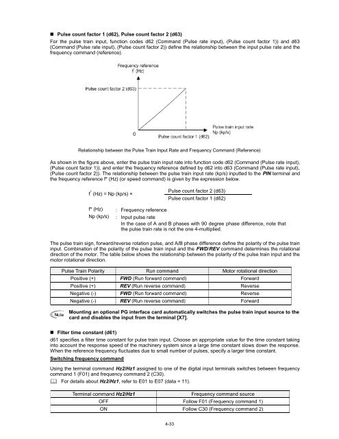
• Pulse count factor 1 (d62), Pulse count factor 2 (d63)<br />
For the pulse train input, function codes d62 (Command (Pulse rate input), (Pulse count factor 1)) and d63<br />
(Command (Pulse rate input), (Pulse count factor 2)) define the relationship between the input pulse rate and the<br />
frequency command (reference).<br />
Relationship between the Pulse Train Input Rate and Frequency Command (Reference)<br />
As shown in the figure above, enter the pulse train input rate into function code d62 (Command (Pulse rate input),<br />
(Pulse count factor 1)), and enter the frequency reference defined by d62 into d63 (Command (Pulse rate input),<br />
(Pulse count factor 2)). The relationship between the pulse train input rate (kp/s) inputted to the PIN terminal and<br />
the frequency reference f* (Hz) (or speed command) is given by the expression below.<br />
f * (Hz) = Np (kp/s) ×<br />
Pulse count factor 2 (d63)<br />
Pulse count factor 1 (d62)<br />
f* (Hz) : Frequency reference<br />
Np (kp/s) : Input pulse rate<br />
In the case of A and B phases with 90 degree phase difference, note that<br />
the pulse train rate is not the one 4-multiplied.<br />
The pulse train sign, forward/reverse rotation pulse, and A/B phase difference define the polarity of the pulse train<br />
input. Combination of the polarity of the pulse train input and the FWD/REV command determines the rotational<br />
direction of the motor. The table below shows the relationship between the polarity of the pulse train input and the<br />
motor rotational direction.<br />
Pulse Train Polarity Run command <strong>Motor</strong> rotational direction<br />
Positive (+) FWD (Run forward command) Forward<br />
Positive (+) REV (Run reverse command) Reverse<br />
Negative (-) FWD (Run forward command) Reverse<br />
Negative (-) REV (Run reverse command) Forward<br />
Mounting an optional PG interface card automatically switches the pulse train input source to the<br />
card and disables the input from the terminal [X7].<br />
• Filter time constant (d61)<br />
d61 specifies a filter time constant for pulse train input. Choose an appropriate value for the time constant taking<br />
into account the response speed of the machinery system since a large time constant slows down the response.<br />
When the reference frequency fluctuates due to small number of pulses, specify a larger time constant.<br />
Switching frequency command<br />
Using the terminal command Hz2/Hz1 assigned to one of the digital input terminals switches between frequency<br />
command 1 (F01) and frequency command 2 (C30).<br />
For details about Hz2/Hz1, refer to E01 to E07 (data = 11).<br />
Terminal command Hz2/Hz1<br />
Frequency command source<br />
OFF Follow F01 (Frequency command 1)<br />
ON Follow C30 (Frequency command 2)<br />
4-33


