

EQ7 Series Instruction Manual - TECO-Westinghouse Motor Company
EQ7 Series Instruction Manual - TECO-Westinghouse Motor Company
EQ7 Series Instruction Manual - TECO-Westinghouse Motor Company

Create successful ePaper yourself
Turn your PDF publications into a flip-book with our unique Google optimized e-Paper software.
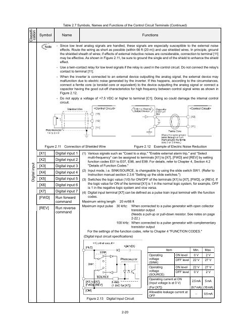
Table 2.7 Symbols, Names and Functions of the Control Circuit Terminals (Continued)<br />
Classification<br />
Symbol Name Functions<br />
- Since low level analog signals are handled, these signals are especially susceptible to the external noise<br />
effects. Route the wiring as short as possible (within 66 ft (20 m)) and use shielded wires. In principle, ground<br />
the shielded sheath of wires; if effects of external inductive noises are considerable, connection to terminal [11]<br />
may be effective. As shown in Figure 2.11, be sure to ground the single end of the shield to enhance the shield<br />
effect.<br />
- Use a twin-contact relay for low level signals if the relay is used in the control circuit. Do not connect the relay's<br />
contact to terminal [11].<br />
- When the inverter is connected to an external device outputting the analog signal, the external device may<br />
malfunction due to electric noise generated by the inverter. If this happens, according to the circumstances,<br />
connect a ferrite core (a toroidal core or equivalent) to the device outputting the analog signal or connect a<br />
capacitor having the good cut-off characteristics for high frequency between control signal wires as shown in<br />
Figure 2.12.<br />
- Do not apply a voltage of +7.5 VDC or higher to terminal [C1]. Doing so could damage the internal control<br />
circuit.<br />
Figure 2.11 Connection of Shielded Wire<br />
Figure 2.12 Example of Electric Noise Reduction<br />
Digital input<br />
[X1]<br />
[X2]<br />
[X3]<br />
Digital input 1<br />
Digital input 2<br />
Digital input 3<br />
(1) Various signals such as "Coast to a stop," "Enable external alarm trip," and "Select<br />
multi-frequency" can be assigned to terminals [X1] to [X7], [FWD] and [REV] by setting<br />
function codes E01 to E07, E98, and E99. For details, refer to Chapter 4, Section 4.2<br />
"Details of Function Codes."<br />
(2) Input mode, i.e. SINK/SOURCE, is changeable by using the slide switch SW1. (Refer to<br />
[X4] Digital input 4<br />
<strong>Instruction</strong> manual section 2.3.6 "Setting up the slide switches.")<br />
[X5] Digital input 5 (3) Switches the logic value (1/0) for ON/OFF of the terminals [X1] to [X7], [FWD], or [REV]. If<br />
[X6] Digital input 6 the logic value for ON of the terminal [X1] is 1 in the normal logic system, for example, OFF<br />
is 1 in the negative logic system and vice versa.<br />
[X7]<br />
[FWD]<br />
Digital input 7<br />
Run forward<br />
(4) Digital input terminal [X7] can be defined as a pulse train input terminal with the function<br />
codes.<br />
command Maximum wiring length 20 m/66 ft<br />
[REV]<br />
Run reverse<br />
command<br />
Maximum input pulse 30 kHz: When connected to a pulse generator with open collector<br />
transistor output<br />
(Needs a pull-up or pull-down resistor. See notes on page<br />
2-22.)<br />
100 kHz: When connected to a pulse generator with complementary<br />
transistor output<br />
For the settings of the function codes, refer to Chapter 4 "FUNCTION CODES."<br />
(Digital input circuit specifications)<br />
Figure 2.13 Digital Input Circuit<br />
Operating<br />
voltage<br />
(SINK)<br />
Operating<br />
voltage<br />
(SOURCE)<br />
Operating current at ON<br />
(Input voltage is at 0 V)<br />
(For [X7])<br />
Item Min. Max.<br />
Allowable leakage current at<br />
OFF<br />
ON level 0 V 2 V<br />
OFF level 22 V 27 V<br />
ON level 22 V 27 V<br />
OFF level 0 V 2 V<br />
2.5 mA 5 mA<br />
(9.7 mA) (16 mA)<br />
<br />
0.5 mA<br />
2-20


