

EQ7 Series Instruction Manual - TECO-Westinghouse Motor Company
EQ7 Series Instruction Manual - TECO-Westinghouse Motor Company
EQ7 Series Instruction Manual - TECO-Westinghouse Motor Company

You also want an ePaper? Increase the reach of your titles
YUMPU automatically turns print PDFs into web optimized ePapers that Google loves.
Wiring for control circuit terminals<br />
For <strong>EQ7</strong>2125-C, <strong>EQ7</strong>2150-C and <strong>EQ7</strong>4250-C to <strong>EQ7</strong>41000-C<br />
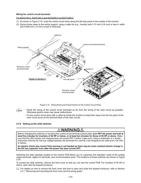
(1) As shown in Figure 2.19, route the control circuit wires along the left side panel to the outside of the inverter.<br />
(2) Secure those wires to the wiring support, using a cable tie (e.g., Insulok) with 0.15 inch (3.8 mm) or less in width<br />
and 0.059 inch (1.5 mm) or less in thickness.<br />
Cable tie<br />
Wiring support<br />
Control circuit terminal block<br />
Wiring for control<br />
circuit terminals<br />
Section A<br />
Details of Section A<br />
Left side panel<br />
Wiring for control<br />
circuit terminals<br />
Figure 2.19 Wiring Route and Fixing Position for the Control Circuit Wires<br />
- Route the wiring of the control circuit terminals as far from the wiring of the main circuit as possible.<br />
Otherwise electric noise may cause malfunctions.<br />
- Fix the control circuit wires with a cable tie inside the inverter to keep them away from the live parts of the<br />
main circuit (such as the terminal block of the main circuit).<br />
2.3.6 Setting up the slide switches<br />
Before changing the switches or touching the control circuit terminal symbol plate, turn OFF the power and wait at<br />
least five minutes for inverters of 40 HP or below, or at least ten minutes for those of 50 HP or above. Make<br />
sure that the LED monitor and charging lamp are turned OFF. Further, make sure, using a multimeter or a similar<br />
instrument, that the DC link bus voltage between the terminals P(+) and N(-) has dropped to the safe level (+25 VDC<br />
or below).<br />
An electric shock may result if this warning is not heeded as there may be some residual electric charge in<br />
the DC bus capacitor even after the power has been turned OFF.<br />
Switching the slide switches located on the control PCB allows you to customize the operation mode of the analog<br />
output terminals, digital I/O terminals, and communications ports. The locations of those switches are shown in Figure<br />
2.20.<br />
To access the slide switches, remove the front cover so that you can see the control PCB. For inverters of 50 HP or<br />
above, open also the keypad enclosure.<br />
For details on how to remove the front cover and how to open and close the keypad enclosure, refer to Section<br />
2.3.1 "Removing and mounting the front cover and the wiring guide."<br />
2-25


