

EQ7 Series Instruction Manual - TECO-Westinghouse Motor Company
EQ7 Series Instruction Manual - TECO-Westinghouse Motor Company
EQ7 Series Instruction Manual - TECO-Westinghouse Motor Company

You also want an ePaper? Increase the reach of your titles
YUMPU automatically turns print PDFs into web optimized ePapers that Google loves.
DC reactor terminals P1 and P (+)<br />
Connect a DC reactor (DCR) to these terminals for power factor correction.<br />
1) Remove the jumper bar from terminals P1 and P(+).<br />
2) Connect an optional DCR to those terminals.<br />
• The wiring length should be 33 ft (10 m) or below.<br />
• Do not remove the jumper bar when a DCR is not used.<br />
• The <strong>EQ7</strong>-2100-C / <strong>EQ7</strong>-4100-C and higher types come with a DCR. Be sure to connect the DCR.<br />
• If a PWM converter is connected to the inverter, no DCR is required.<br />
Be sure to connect an optional DC reactor (DCR) when the capacity of the power supply transformer exceeds 500<br />
kVA and is 10 times or more the inverter rated capacity.<br />
Otherwise, a fire could occur.<br />
DC braking resistor terminals P(+) and DB (for inverters of 40 HP or below)<br />
Capacity<br />
(HP)<br />
Braking transistor<br />
Built-in DC braking<br />
resistor (DBR)<br />
Optional devices<br />
Option mounting<br />
steps required<br />
0.5 to 15 Built-in Built-in<br />
External DC braking resistor<br />
(with a larger capacity)<br />
1), 2), 3)<br />
20 to 40 Built-in None External DC braking resistor 2), 3)<br />
For inverters of 15 HP or below, if the capacity of the built-in DC braking resistor (DBR) is insufficient since the inverter<br />
undergoes frequent start/stop or heavy inertial load, mount an optional external DC braking resistor (DBR) with a larger<br />
capacity to increase the braking capability, using the following steps. Before mounting the external DBR, remove the<br />
built-in DBR.<br />
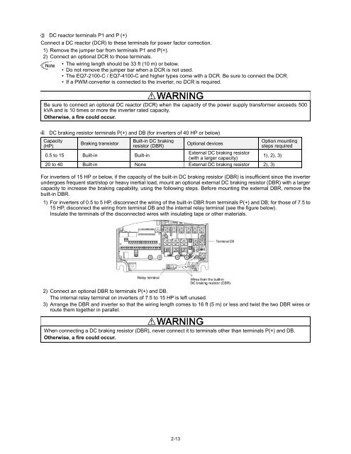
1) For inverters of 0.5 to 5 HP, disconnect the wiring of the built-in DBR from terminals P(+) and DB; for those of 7.5 to<br />
15 HP, disconnect the wiring from terminal DB and the internal relay terminal (see the figure below).<br />
Insulate the terminals of the disconnected wires with insulating tape or other materials.<br />
2) Connect an optional DBR to terminals P(+) and DB.<br />
The internal relay terminal on inverters of 7.5 to 15 HP is left unused.<br />
3) Arrange the DBR and inverter so that the wiring length comes to 16 ft (5 m) or less and twist the two DBR wires or<br />
route them together in parallel.<br />
When connecting a DC braking resistor (DBR), never connect it to terminals other than terminals P(+) and DB.<br />
Otherwise, a fire could occur.<br />
2-13


