

EQ7 Series Instruction Manual - TECO-Westinghouse Motor Company
EQ7 Series Instruction Manual - TECO-Westinghouse Motor Company
EQ7 Series Instruction Manual - TECO-Westinghouse Motor Company

You also want an ePaper? Increase the reach of your titles
YUMPU automatically turns print PDFs into web optimized ePapers that Google loves.
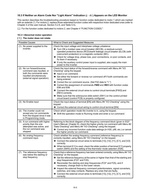
10.3 If Neither an Alarm Code Nor "Light Alarm" Indication ( ) Appears on the LED Monitor<br />
This section describes the troubleshooting procedure based on function codes dedicated to motor 1 which are marked<br />
with an asterisk (*). For motors 2, replace those asterisked function codes with respective motor dedicated ones (refer to<br />
Chapter 4 of the user manual, Section 5.2.6, and Table 5.5).<br />
For the function codes dedicated to motors 2, see Chapter 4 "FUNCTION CODES."<br />
10.3.1 Abnormal motor operation<br />
[ 1 ] The motor does not rotate.<br />
Possible Causes<br />
(1) No power supplied to the<br />
inverter.<br />
(2) No run forward/reverse<br />
command was inputted, or<br />
both the commands were<br />
inputted simultaneously<br />
(external signal operation).<br />
What to Check and Suggested Measures<br />
Check the input voltage and interphase voltage unbalance.<br />
Turn ON a molded case circuit breaker (MCCB), a residual-currentoperated<br />
protective device (RCD)/earth leakage circuit breaker (ELCB) (with<br />
overcurrent protection) or a magnetic contactor (MC).<br />
Check for voltage drop, phase loss, poor connections, or poor contacts, and<br />
fix them if necessary.<br />
If only the auxiliary control power input is supplied, also supply the main<br />
power to the inverter.<br />
Check the input status of the forward/reverse command with Menu #4 "I/O<br />
Checking" using the keypad.<br />
Input a run command.<br />
Set either the forward or reverse run command off if both commands are<br />
being entered.<br />
Correct the run command source. (Set F02 data to "1.")<br />
Correct the assignment of commands FWD and REV with function codes<br />
E98 and E99.<br />
Connect the external circuit wires to control circuit terminals [FWD] and<br />
[REV] correctly.<br />
Make sure that the sink/source slide switch (SW1) on the control printed<br />
circuit board (control PCB) is properly configured.<br />
(3) No Enable input Check the input status of terminal [EN] with Menu #4 "I/O Checking" using the<br />
keypad.<br />
Correct the external circuit wiring to control circuit terminal [EN].<br />
(4) The inverter could not<br />
accept any run commands<br />
from the keypad since it was<br />
in Programming mode.<br />
(5) A run command with higher<br />
priority than the one<br />
attempted was active, and<br />
the run command was<br />
stopped.<br />
(6) No analog frequency<br />
command input.<br />
(7) The reference frequency<br />
was below the starting or<br />
stop frequency.<br />
Check which operation mode the inverter is in, using the keypad.<br />
Shift the operation mode to Running mode and enter a run command.<br />
Referring to the block diagram of the frequency command block (given in <strong>EQ7</strong><br />
User's <strong>Manual</strong>, Chapter 6), check the higher priority run command with Menu #2<br />
"Data Checking" and Menu #4 "I/O Checking" using the keypad.<br />
Correct any incorrect function code data settings (in H30, y98, etc.) or cancel<br />
the higher priority run command.<br />
Check whether the analog frequency command (reference frequency) is<br />
correctly inputted, using Menu #4 "I/O Checking" on the keypad.<br />
Connect the external circuit wires to terminals [13], [12], [11], [C1], and [V2]<br />
correctly.<br />
When terminal [C1] is used, check the slider position of terminal [C1] property<br />
switch (SW5) and the setting of the thermistor mode selection (H26).<br />
Check that a reference frequency has been entered correctly, using Menu #4 "I/O<br />
Checking" on the keypad.<br />
Set the reference frequency at the same or higher than that of the starting and<br />
stop frequencies (F23* and F25).<br />
Reconsider the starting and stop frequencies (F23* and F25), and if<br />
necessary, change them to the lower values.<br />
Inspect the external frequency command potentiometers, signal converters,<br />
switches, and relay contacts. Replace any ones that are faulty.<br />
Connect the external circuit wires to terminals [13], [12], [11], [C1], and [V2]<br />
correctly.<br />
10-5


