

EQ7 Series Instruction Manual - TECO-Westinghouse Motor Company
EQ7 Series Instruction Manual - TECO-Westinghouse Motor Company
EQ7 Series Instruction Manual - TECO-Westinghouse Motor Company

You also want an ePaper? Increase the reach of your titles
YUMPU automatically turns print PDFs into web optimized ePapers that Google loves.
• Inverter running -- RUN (Function code data = 0)<br />
Inverter output on -- RUN2 (Function code data = 35)<br />
These output signals tell the external equipment that the inverter is running at a starting frequency or higher.<br />
If assigned in negative logic (Active OFF), these signals can be used to tell the "Inverter being stopped" state.<br />
Output signal Basic function Remarks<br />
RUN<br />
RUN2<br />
These signals come ON when the inverter is<br />
running.<br />
Under V/f control:<br />
These signals come ON if the inverter output<br />
frequency exceeds the starting frequency, and go<br />
OFF if it drops below the stop frequency. The RUN<br />
signal can also be used as a "Speed valid" signal<br />
DNZS.<br />
Goes OFF even during DC braking<br />
or dew condensation prevention.<br />
Comes ON even during DC<br />
braking, pre-exciting, zero speed<br />
control, or dew condensation<br />
prevention.<br />
Under vector control, both RUN and RUN2 come ON when zero speed control or servo-lock function is enabled.<br />
• Undervoltage detected (Inverter stopped) -- LU (Function code data = 3)<br />
This output signal comes ON when the DC link bus voltage of the inverter drops below the specified undervoltage<br />
level, and it goes OFF when the voltage exceeds the level.<br />
This signal is ON also when the undervoltage protective function is activated so that the motor is in an abnormal<br />
stop state (e.g., tripped).<br />
When this signal is ON, a run command is disabled if given.<br />
• Torque polarity detected -- B/D (Function code data = 4)<br />
The inverter issues the driving or braking polarity signal to this digital output judging from the internally calculated<br />
torque or torque command. This signal goes OFF when the detected torque is a driving one, and it goes ON when<br />
it is a braking one.<br />
• Inverter output limiting -- IOL (Function code data = 5)<br />
Inverter output limiting with delay -- IOL2 (Function code data = 22)<br />
The output signal IOL comes ON when the inverter is limiting the output frequency by activating any of the<br />
following actions (minimum width of the output signal: 100 ms). The output signal IOL2 comes ON when any of the<br />
following output limiting operation continues for 20 ms or more.<br />
• Torque limiting (F40, F41, E16 and E17, Maximum internal value)<br />
• Current limiting by software (F43 and F44)<br />
• Instantaneous overcurrent limiting by hardware (H12 = 1)<br />
• Automatic deceleration (Anti-regenerative control) (H69)<br />
When the IOL signal is ON, it may mean that the output frequency may have deviated from the frequency<br />
specified by the frequency command because of this limiting function.<br />
• Keypad operation enabled -- KP (Function code data = 8)<br />
This output signal comes ON when the keypad is specified as a run command source.<br />
• Inverter ready to run -- RDY (Function code data = 10)<br />
This output signal comes ON when the inverter becomes ready to run by completing hardware preparation (such<br />
as initial charging of DC link bus capacitors and initialization of the control circuit) and no protective functions are<br />
activated.<br />
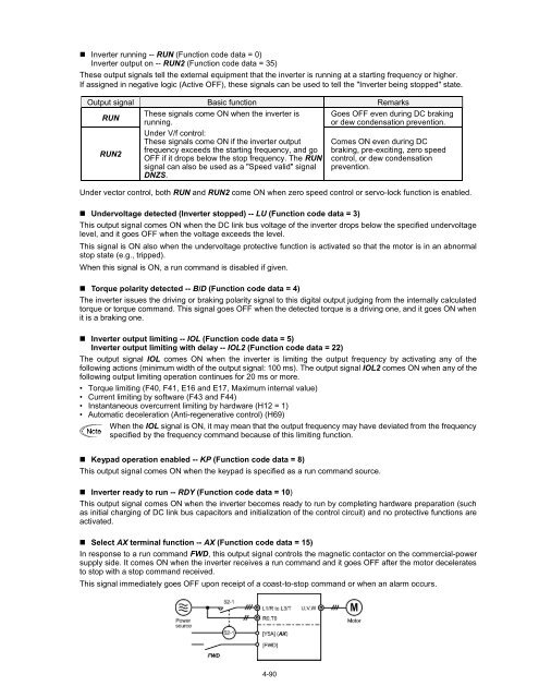
• Select AX terminal function -- AX (Function code data = 15)<br />
In response to a run command FWD, this output signal controls the magnetic contactor on the commercial-power<br />
supply side. It comes ON when the inverter receives a run command and it goes OFF after the motor decelerates<br />
to stop with a stop command received.<br />
This signal immediately goes OFF upon receipt of a coast-to-stop command or when an alarm occurs.<br />
4-90


