

EQ7 Series Instruction Manual - TECO-Westinghouse Motor Company
EQ7 Series Instruction Manual - TECO-Westinghouse Motor Company
EQ7 Series Instruction Manual - TECO-Westinghouse Motor Company

Create successful ePaper yourself
Turn your PDF publications into a flip-book with our unique Google optimized e-Paper software.
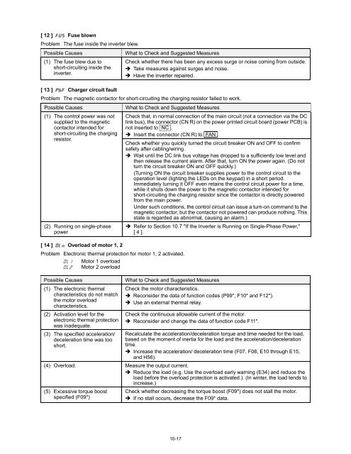
[ 12 ] Fuse blown<br />
Problem The fuse inside the inverter blew.<br />
Possible Causes<br />
(1) The fuse blew due to<br />
short-circuiting inside the<br />
inverter.<br />
[ 13 ] Charger circuit fault<br />
What to Check and Suggested Measures<br />
Check whether there has been any excess surge or noise coming from outside.<br />
Take measures against surges and noise.<br />
Have the inverter repaired.<br />
Problem The magnetic contactor for short-circuiting the charging resistor failed to work.<br />
Possible Causes<br />
(1) The control power was not<br />
supplied to the magnetic<br />
contactor intended for<br />
short-circuiting the charging<br />
resistor.<br />
(2) Running on single-phase<br />
power<br />
[ 14 ] Overload of motor 1, 2<br />
What to Check and Suggested Measures<br />
Problem Electronic thermal protection for motor 1, 2 activated.<br />
<strong>Motor</strong> 1 overload<br />
<strong>Motor</strong> 2 overload<br />
Possible Causes<br />
(1) The electronic thermal<br />
characteristics do not match<br />
the motor overload<br />
characteristics.<br />
(2) Activation level for the<br />
electronic thermal protection<br />
was inadequate.<br />
(3) The specified acceleration/<br />
deceleration time was too<br />
short.<br />
Check that, in normal connection of the main circuit (not a connection via the DC<br />
link bus), the connector (CN R) on the power printed circuit board (power PCB) is<br />
not inserted to NC .<br />
Insert the connector (CN R) to FAN .<br />
Check whether you quickly turned the circuit breaker ON and OFF to confirm<br />
safety after cabling/wiring.<br />
Wait until the DC link bus voltage has dropped to a sufficiently low level and<br />
then release the current alarm. After that, turn ON the power again. (Do not<br />
turn the circuit breaker ON and OFF quickly.)<br />
(Turning ON the circuit breaker supplies power to the control circuit to the<br />
operation level (lighting the LEDs on the keypad) in a short period.<br />
Immediately turning it OFF even retains the control circuit power for a time,<br />
while it shuts down the power to the magnetic contactor intended for<br />
short-circuiting the charging resistor since the contactor is directly powered<br />
from the main power.<br />
Under such conditions, the control circuit can issue a turn-on command to the<br />
magnetic contactor, but the contactor not powered can produce nothing. This<br />
state is regarded as abnormal, causing an alarm.)<br />
Refer to Section 10.7 "If the Inverter is Running on Single-Phase Power,"<br />
[ 4 ].<br />
What to Check and Suggested Measures<br />
Check the motor characteristics.<br />
Reconsider the data of function codes (P99*, F10* and F12*).<br />
Use an external thermal relay.<br />
Check the continuous allowable current of the motor.<br />
Reconsider and change the data of function code F11*.<br />
Recalculate the acceleration/deceleration torque and time needed for the load,<br />
based on the moment of inertia for the load and the acceleration/deceleration<br />
time.<br />
Increase the acceleration/ deceleration time (F07, F08, E10 through E15,<br />
and H56).<br />
(4) Overload. Measure the output current.<br />
Reduce the load (e.g. Use the overload early warning (E34) and reduce the<br />
load before the overload protection is activated.). (In winter, the load tends to<br />
increase.)<br />
(5) Excessive torque boost<br />
specified (F09*)<br />
Check whether decreasing the torque boost (F09*) does not stall the motor.<br />
If no stall occurs, decrease the F09* data.<br />
10-17


