

EQ7 Series Instruction Manual - TECO-Westinghouse Motor Company
EQ7 Series Instruction Manual - TECO-Westinghouse Motor Company
EQ7 Series Instruction Manual - TECO-Westinghouse Motor Company

You also want an ePaper? Increase the reach of your titles
YUMPU automatically turns print PDFs into web optimized ePapers that Google loves.
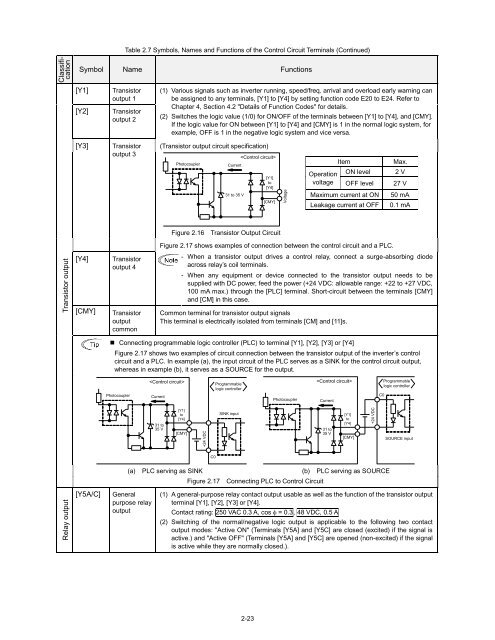
Table 2.7 Symbols, Names and Functions of the Control Circuit Terminals (Continued)<br />
Classification<br />
Symbol Name Functions<br />
[Y1]<br />
[Y2]<br />
Transistor<br />
output 1<br />
Transistor<br />
output 2<br />
(1) Various signals such as inverter running, speed/freq. arrival and overload early warning can<br />
be assigned to any terminals, [Y1] to [Y4] by setting function code E20 to E24. Refer to<br />
Chapter 4, Section 4.2 "Details of Function Codes" for details.<br />
(2) Switches the logic value (1/0) for ON/OFF of the terminals between [Y1] to [Y4], and [CMY].<br />
If the logic value for ON between [Y1] to [Y4] and [CMY] is 1 in the normal logic system, for<br />
example, OFF is 1 in the negative logic system and vice versa.<br />
[Y3]<br />
Transistor<br />
output 3<br />
(Transistor output circuit specification)<br />
Photocoupler<br />
Current<br />
31 to 35 V<br />
<br />
[Y1]<br />
to<br />
[Y4]<br />
[CMY]<br />
Voltage<br />
Operation<br />
voltage<br />
Item<br />
ON level<br />
OFF level<br />
Maximum current at ON<br />
Leakage current at OFF<br />
Max.<br />
2 V<br />
27 V<br />
50 mA<br />
0.1 mA<br />
Figure 2.16 Transistor Output Circuit<br />
Figure 2.17 shows examples of connection between the control circuit and a PLC.<br />
Transistor output<br />
[Y4]<br />
[CMY]<br />
Transistor<br />
output 4<br />
Transistor<br />
output<br />
common<br />
- When a transistor output drives a control relay, connect a surge-absorbing diode<br />
across relay’s coil terminals.<br />
- When any equipment or device connected to the transistor output needs to be<br />
supplied with DC power, feed the power (+24 VDC: allowable range: +22 to +27 VDC,<br />
100 mA max.) through the [PLC] terminal. Short-circuit between the terminals [CMY]<br />
and [CM] in this case.<br />
Common terminal for transistor output signals<br />
This terminal is electrically isolated from terminals [CM] and [11]s.<br />
• Connecting programmable logic controller (PLC) to terminal [Y1], [Y2], [Y3] or [Y4]<br />
Figure 2.17 shows two examples of circuit connection between the transistor output of the inverter’s control<br />
circuit and a PLC. In example (a), the input circuit of the PLC serves as a SINK for the control circuit output,<br />
whereas in example (b), it serves as a SOURCE for the output.<br />
Photocoupler<br />
<br />
Current<br />
Programmable<br />
logic controller<br />
Photocoupler<br />
<br />
Current<br />
C0<br />
Programmable<br />
logic controller<br />
31 to<br />
35 V<br />
[Y1]<br />
to<br />
[Y4]<br />
[CMY]<br />
+24 VDC<br />
SINK input<br />
31 to<br />
35 V<br />
[Y1]<br />
to<br />
[Y4]<br />
[CMY]<br />
+24 VDC<br />
SOURCE input<br />
C0<br />
(a) PLC serving as SINK<br />
Figure 2.17 Connecting PLC to Control Circuit<br />
(b) PLC serving as SOURCE<br />
Relay output<br />
[Y5A/C]<br />
General<br />
purpose relay<br />
output<br />
(1) A general-purpose relay contact output usable as well as the function of the transistor output<br />
terminal [Y1], [Y2], [Y3] or [Y4].<br />
Contact rating: 250 VAC 0.3 A, cos = 0.3, 48 VDC, 0.5 A<br />
(2) Switching of the normal/negative logic output is applicable to the following two contact<br />
output modes: "Active ON" (Terminals [Y5A] and [Y5C] are closed (excited) if the signal is<br />
active.) and "Active OFF" (Terminals [Y5A] and [Y5C] are opened (non-excited) if the signal<br />
is active while they are normally closed.).<br />
2-23


