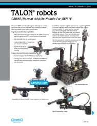
Adept Quattro s650H Robot
Adept Quattro s650H Robot User's Guide - Asimo.pl
Adept Quattro s650H Robot User's Guide - Asimo.pl
- No tags were found...

You also want an ePaper? Increase the reach of your titles
YUMPU automatically turns print PDFs into web optimized ePapers that Google loves.
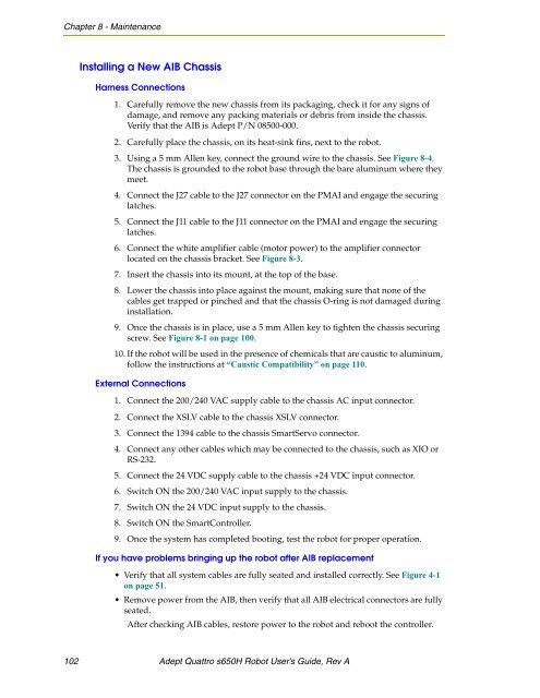
Chapter 8 - Maintenance<br />
Installing a New AIB Chassis<br />
Harness Connections<br />
1. Carefully remove the new chassis from its packaging, check it for any signs of<br />
damage, and remove any packing materials or debris from inside the chassis.<br />
Verify that the AIB is <strong>Adept</strong> P/N 08500-000.<br />
2. Carefully place the chassis, on its heat-sink fins, next to the robot.<br />
3. Using a 5 mm Allen key, connect the ground wire to the chassis. See Figure 8-4.<br />
The chassis is grounded to the robot base through the bare aluminum where they<br />
meet.<br />
4. Connect the J27 cable to the J27 connector on the PMAI and engage the securing<br />
latches.<br />
5. Connect the J11 cable to the J11 connector on the PMAI and engage the securing<br />
latches.<br />
6. Connect the white amplifier cable (motor power) to the amplifier connector<br />
located on the chassis bracket. See Figure 8-3.<br />
7. Insert the chassis into its mount, at the top of the base.<br />
8. Lower the chassis into place against the mount, making sure that none of the<br />
cables get trapped or pinched and that the chassis O-ring is not damaged during<br />
installation.<br />
9. Once the chassis is in place, use a 5 mm Allen key to tighten the chassis securing<br />
screw. See Figure 8-1 on page 100.<br />
10. If the robot will be used in the presence of chemicals that are caustic to aluminum,<br />
follow the instructions at “Caustic Compatibility” on page 110.<br />
External Connections<br />
1. Connect the 200/240 VAC supply cable to the chassis AC input connector.<br />
2. Connect the XSLV cable to the chassis XSLV connector.<br />
3. Connect the 1394 cable to the chassis SmartServo connector.<br />
4. Connect any other cables which may be connected to the chassis, such as XIO or<br />
RS-232.<br />
5. Connect the 24 VDC supply cable to the chassis +24 VDC input connector.<br />
6. Switch ON the 200/240 VAC input supply to the chassis.<br />
7. Switch ON the 24 VDC input supply to the chassis.<br />
8. Switch ON the SmartController.<br />
9. Once the system has completed booting, test the robot for proper operation.<br />
If you have problems bringing up the robot after AIB replacement<br />
• Verify that all system cables are fully seated and installed correctly. See Figure 4-1<br />
on page 51.<br />
• Remove power from the AIB, then verify that all AIB electrical connectors are fully<br />
seated.<br />
After checking AIB cables, restore power to the robot and reboot the controller.<br />
102 <strong>Adept</strong> <strong>Quattro</strong> <strong>s650H</strong> <strong>Robot</strong> User’s Guide, Rev A