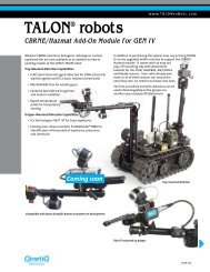
Adept Quattro s650H Robot
Adept Quattro s650H Robot User's Guide - Asimo.pl
Adept Quattro s650H Robot User's Guide - Asimo.pl
- No tags were found...

You also want an ePaper? Increase the reach of your titles
YUMPU automatically turns print PDFs into web optimized ePapers that Google loves.
List of Figures<br />
Figure 1-1. <strong>Adept</strong> <strong>Quattro</strong> <strong>s650H</strong> <strong>Robot</strong> . . . . . . . . . . . . . . . . . . . . . . . . . . . . . . . . . . . . . . 13<br />
Figure 1-2. Major <strong>Robot</strong> Components, Isometric View . . . . . . . . . . . . . . . . . . . . . . . . . . 14<br />
Figure 1-3. <strong>Adept</strong> AIB . . . . . . . . . . . . . . . . . . . . . . . . . . . . . . . . . . . . . . . . . . . . . . . . . . . . . . 15<br />
Figure 1-4. <strong>Robot</strong> Inner Arm . . . . . . . . . . . . . . . . . . . . . . . . . . . . . . . . . . . . . . . . . . . . . . . . 15<br />
Figure 1-5. Ball Joints between Inner and Outer Arms . . . . . . . . . . . . . . . . . . . . . . . . . . . 16<br />
Figure 1-6. 185° Platform, Top View . . . . . . . . . . . . . . . . . . . . . . . . . . . . . . . . . . . . . . . . . . 18<br />
Figure 1-7. 185° Platform, Bottom View . . . . . . . . . . . . . . . . . . . . . . . . . . . . . . . . . . . . . . . 18<br />
Figure 1-8. 60° Platform, Top View . . . . . . . . . . . . . . . . . . . . . . . . . . . . . . . . . . . . . . . . . . . 19<br />
Figure 1-9. 60° Platform, Bottom View . . . . . . . . . . . . . . . . . . . . . . . . . . . . . . . . . . . . . . . . 19<br />
Figure 1-10. <strong>Adept</strong> SmartController CX . . . . . . . . . . . . . . . . . . . . . . . . . . . . . . . . . . . . . . . . 20<br />
Figure 2-1. Electrical and Thermal Warning Labels on AIB Chassis . . . . . . . . . . . . . . . . . 24<br />
Figure 3-1. <strong>Quattro</strong> Shipping Crate . . . . . . . . . . . . . . . . . . . . . . . . . . . . . . . . . . . . . . . . . . 36<br />
Figure 3-2. Crate with Front Panel/Sides Removed . . . . . . . . . . . . . . . . . . . . . . . . . . . . . 36<br />
Figure 3-3. Sample <strong>Quattro</strong> Mounting Frame . . . . . . . . . . . . . . . . . . . . . . . . . . . . . . . . . . 38<br />
Figure 3-4. Location of Slings for Lifting <strong>Robot</strong> Base . . . . . . . . . . . . . . . . . . . . . . . . . . . . . 42<br />
Figure 3-5. Major <strong>Robot</strong> Components, Top View . . . . . . . . . . . . . . . . . . . . . . . . . . . . . . . 45<br />
Figure 3-6. Platform Orientation Labeling . . . . . . . . . . . . . . . . . . . . . . . . . . . . . . . . . . . . . 46<br />
Figure 3-7. Inner Arm Ball Studs . . . . . . . . . . . . . . . . . . . . . . . . . . . . . . . . . . . . . . . . . . . . . . 47<br />
Figure 3-8. Ball Joint Assembly . . . . . . . . . . . . . . . . . . . . . . . . . . . . . . . . . . . . . . . . . . . . . . 47<br />
Figure 3-9. Installing Ball Joints . . . . . . . . . . . . . . . . . . . . . . . . . . . . . . . . . . . . . . . . . . . . . . 48<br />
Figure 3-10. Spring Hook Gap Dimension . . . . . . . . . . . . . . . . . . . . . . . . . . . . . . . . . . . . . . 49<br />
Figure 3-11. Spring Hook in Bushing . . . . . . . . . . . . . . . . . . . . . . . . . . . . . . . . . . . . . . . . . . . 49<br />
Figure 4-1. System Cable Diagram . . . . . . . . . . . . . . . . . . . . . . . . . . . . . . . . . . . . . . . . . . 51<br />
Figure 4-2. <strong>Robot</strong> Interface Panel . . . . . . . . . . . . . . . . . . . . . . . . . . . . . . . . . . . . . . . . . . . 53<br />
Figure 4-3. User-Supplied 24 VDC Cable . . . . . . . . . . . . . . . . . . . . . . . . . . . . . . . . . . . . . . 56<br />
Figure 4-4. Typical AC Power Installation with Single-Phase Supply . . . . . . . . . . . . . . . . 58<br />
Figure 4-5. Single-Phase AC Power Installation from a Three-Phase AC Supply . . . . . . 59<br />
Figure 4-6. AC Power Mating Connector . . . . . . . . . . . . . . . . . . . . . . . . . . . . . . . . . . . . . 60<br />
Figure 5-1. <strong>Robot</strong> Status Display Panel . . . . . . . . . . . . . . . . . . . . . . . . . . . . . . . . . . . . . . . . 63<br />
Figure 5-2. Connecting Digital I/O to the System . . . . . . . . . . . . . . . . . . . . . . . . . . . . . . . 66<br />
Figure 5-3. Typical User Wiring for XIO Input Signals . . . . . . . . . . . . . . . . . . . . . . . . . . . . . 70<br />
Figure 5-4. Typical User Wiring for XIO Output Signals . . . . . . . . . . . . . . . . . . . . . . . . . . . 72<br />
Figure 5-5. Optional XIO Breakout Cable . . . . . . . . . . . . . . . . . . . . . . . . . . . . . . . . . . . . . 72<br />
Figure 5-6. Typical Startup Screen . . . . . . . . . . . . . . . . . . . . . . . . . . . . . . . . . . . . . . . . . . . 75<br />
Figure 5-7. 185° Platform Ambiguity Zones . . . . . . . . . . . . . . . . . . . . . . . . . . . . . . . . . . . . 78<br />
Figure 5-8. Invalid Move . . . . . . . . . . . . . . . . . . . . . . . . . . . . . . . . . . . . . . . . . . . . . . . . . . . 78<br />
Figure 5-9. Valid Move . . . . . . . . . . . . . . . . . . . . . . . . . . . . . . . . . . . . . . . . . . . . . . . . . . . . . 79<br />
Figure 7-1. Top Dimensions, Work Envelope, and Mounting Hole Pattern . . . . . . . . . . 83<br />
Figure 7-2. Work Envelope, Side View . . . . . . . . . . . . . . . . . . . . . . . . . . . . . . . . . . . . . . . . 84<br />
<strong>Adept</strong> <strong>Quattro</strong> <strong>s650H</strong> <strong>Robot</strong> User’s Guide, Rev A 11