- Page 1 and 2:
�� complete proGram www.bti-Gro
- Page 3 and 4:
Sealants and PU foams Workshop chem
- Page 5 and 6:
DOWEL TECHNOLOGY ����� Ny
- Page 7 and 8:
1006 Dowel technology ����
- Page 9 and 10:
1006 Standard fixings 1) For permit
- Page 11 and 12:
1006 How dowels work Dowels have th
- Page 13 and 14:
1006 Model B Model BL ����
- Page 15 and 16:
1006 ProCon X plus With flange With
- Page 17 and 18:
1006 ����� Express nail E
- Page 19 and 20:
1006 drill or hammer screw in Atten
- Page 21 and 22:
1006 Mounting pliers, straight Moun
- Page 23 and 24:
1006 LS LD Pull-out value in kN* LP
- Page 25 and 26:
1006 Assembly instruction: Make sur
- Page 27 and 28:
1006 HWP HWP in System-Eurobox 400
- Page 29 and 30:
1006 Z-21.2-2 1 Monitored Fire test
- Page 31 and 32:
1006 Nail plug B-SD…FK Flat flush
- Page 33 and 34:
1006 Flat-round cap for metal sleev
- Page 35 and 36:
1006 A firm anchoring of the insula
- Page 37 and 38:
1006 ����� Insulation uni
- Page 39 and 40:
1006 g With welded ring eye and woo
- Page 41 and 42:
1006 ����� Different fast
- Page 43 and 44:
1006 ����� Multi-Monti as
- Page 45 and 46:
1006 ����� Technical syst
- Page 47 and 48:
1006 Drill the borehole Hammer in t
- Page 49 and 50:
1006 Steel yellow ����� C
- Page 51 and 52:
1006 d a a a r Temperature Hardenin
- Page 53 and 54:
1006 KU- and metal sieve sleeves fo
- Page 55 and 56:
1006 ����� universal bond
- Page 57 and 58:
1006 ����� upat bonding t
- Page 59 and 60:
����� roof ventilation Ad
- Page 61 and 62:
1006 Mounting systems for roofs and
- Page 63 and 64:
1006 Safety features: • complies
- Page 65 and 66:
1006 Technical data Material stretc
- Page 67 and 68:
1006 'a' ����� Valley tro
- Page 69 and 70:
1006 Ridge end cover FES/ FES-Alu g
- Page 71 and 72:
1006 ����� AL-Vario the s
- Page 73 and 74:
1006 � Joint sealing tape � Vap
- Page 75 and 76:
1006 � Clamping felt � Vapor se
- Page 77 and 78:
1006 ����� Roof membranes
- Page 79 and 80:
1006 ����� Roof membrane
- Page 81 and 82:
1006 the professional window instal
- Page 83 and 84:
1006 the adhesive must be applied i
- Page 85 and 86:
1006 Window with internal rabbet Se
- Page 87 and 88:
1006 ����� Multi primer u
- Page 89 and 90:
1006 4W-toptec 45/11.5 plus Blade m
- Page 91 and 92:
1006 ����� Additional mat
- Page 93 and 94:
1006 The details specified in this
- Page 95 and 96:
1006 ����� Wood connector
- Page 97 and 98:
1006 BFA 300 x 2.0 �����
- Page 99 and 100:
1006 ����� bracket connec
- Page 101 and 102:
1006 Type D Drill template Type D 0
- Page 103 and 104:
Standard roof hook Flex roof hook 1
- Page 105 and 106:
1006 S O L A R M O u n t i n g �
- Page 107 and 108:
1006 S O L A R M O u n t i n g �
- Page 109 and 110:
1006 S O L A R M O u n t i n g �
- Page 111 and 112:
����� Drill and chiseling
- Page 113 and 114:
1006 Drilling, sawing, grinding, cu
- Page 115 and 116:
1006 Drilling, sawing, grinding, cu
- Page 117 and 118:
1006 SDS plus Item Unit dia. Workin
- Page 119 and 120:
1006 Improved design! SDS max �
- Page 121 and 122:
1006 SDS max chisel bit Bullpoint b
- Page 123 and 124:
1006 SDS plus only to be bored when
- Page 125 and 126:
1006 � � � � � � �
- Page 127 and 128:
1006 ����� DDS Extraction
- Page 129 and 130:
1006 Note: Your bTI sales engineer
- Page 131 and 132:
1006 ����� Drill stands 2
- Page 133 and 134:
1006 ����� Spot-drill ass
- Page 135 and 136:
1006 SW adapter SW point on m16 poi
- Page 137 and 138:
1006 Item Unit dia. Working Total n
- Page 139 and 140:
1006 Centering cylinder, especially
- Page 141 and 142:
1006 Tool steel sharpened Arbor-mou
- Page 143 and 144:
1006 only to be bored when turning,
- Page 145 and 146:
1006 L 1 L 2 Item Unit dia. L1 L2 n
- Page 147 and 148:
1006 L 1 L 2 Item Unit dia. L1 L2 n
- Page 149 and 150:
1006 one-sided, DIN 1897 double-sid
- Page 151 and 152:
1006 Usage instructions for bTI thr
- Page 153 and 154:
1006 ����� Threaded cutte
- Page 155 and 156:
1006 Type PG Item no.: 425044 Item
- Page 157 and 158:
1006 ����� Conical and de
- Page 159 and 160:
1006 ����� Plate holes as
- Page 161 and 162:
1006 Shaft and label color metal Wo
- Page 163 and 164:
1006 overview of jigsaw blades meta
- Page 165 and 166:
1006 Item No. Wood basicCut m 3.0/7
- Page 167 and 168:
1006 Item No. Wood SolidCut W 4.0/7
- Page 169 and 170:
1006 overview of reciprocating saw
- Page 171 and 172:
1006 Item No. metal LonglifeCut m 1
- Page 173 and 174:
1006 Item No. ����� Unit
- Page 175 and 176:
1006 In chapter Suitable saws 09 b
- Page 177 and 178:
1006 material Saw hard metal cylind
- Page 179 and 180:
1006 ����� Cylindrical sa
- Page 181 and 182:
1006 ••• very good cutting re
- Page 183 and 184:
1006 ����� master-Cut cir
- Page 185 and 186:
1006 ����� Uni-Cut circul
- Page 187 and 188:
1006 ����� Hard metal rev
- Page 189 and 190:
1006 For supporting disk straight r
- Page 191 and 192:
1006 ����� Sand paper rol
- Page 193 and 194:
1006 For use in the following machi
- Page 195 and 196:
1006 For use in the following machi
- Page 197 and 198:
1006 For use in the following machi
- Page 199 and 200:
1006 For use in the following machi
- Page 201 and 202:
1006 ����� Sanding belt F
- Page 203 and 204:
1006 ����� one-sided parq
- Page 205 and 206:
1006 ����� Parquet pad Fo
- Page 207 and 208:
1006 For use in the following machi
- Page 209 and 210:
1006 ����� Sanding mat, r
- Page 211 and 212:
1006 ����� Cutting off an
- Page 213 and 214:
1006 ����� Cutting wheel
- Page 215 and 216:
1006 ����� bSX TurboCut m
- Page 217 and 218:
1006 ����� basic brick Ra
- Page 219 and 220:
1006 overview of diamond cutting wh
- Page 221 and 222:
1006 ����� DTS Coolmax Hi
- Page 223 and 224:
1006 ����� DTS Coolmax Sp
- Page 225 and 226:
1006 ����� DTS Window Spe
- Page 227 and 228:
1006 ����� DTS Asphalt We
- Page 229 and 230:
1006 ����� Diamond cup wh
- Page 231 and 232:
����� For woodworking: Co
- Page 233 and 234:
1006 Screwing and fastening technol
- Page 235 and 236:
1006 A Cover cap for various applic
- Page 237 and 238:
1006 Page 287 Steel nail Countersun
- Page 239 and 240:
1006 g 12 mm cap-dia. g Ridge dia.
- Page 241 and 242:
1006 g 15 mm cap dia. g For screw w
- Page 243 and 244:
1006 ����� Water slot cap
- Page 245 and 246:
1006 ����� Winbag Simple
- Page 247 and 248:
1006 ����� toptec ® dist
- Page 249 and 250:
1006 Blade dimensions: Screw with i
- Page 251 and 252:
1006 Ideal for narrow notches and s
- Page 253 and 254:
1006 TX 25 Milling ribs ® Using th
- Page 255 and 256:
1006 blue galvanized blue galvanize
- Page 257 and 258:
1006 "Topcoat" coating 7,0 4,2 7,0
- Page 259 and 260:
1006 Examples of application: singl
- Page 261 and 262:
1006 Rolling shutter guideways Wind
- Page 263 and 264:
1006 Bit, TX Z-9.1-600 DoTec, Seko,
- Page 265 and 266:
1006 Countersunk head Raised counte
- Page 267 and 268:
1006 Bit, Pozidriv PZ 2 PZ 3 Counte
- Page 269 and 270:
1006 Bit, TX TX 25 TX 25 Countersun
- Page 271 and 272:
1006 Bit, Pozidriv PZ 1 PZ 2 PZ 2 P
- Page 273 and 274:
1006 quick and easy screwing along
- Page 275 and 276:
1006 Force 60% higher torque travel
- Page 277 and 278:
1006 ����� Terra-Vent-Sys
- Page 279 and 280:
1006 Multipurpose screw Electrical
- Page 281 and 282:
1006 Baufix dry wall screw SBS Made
- Page 283 and 284:
1006 Wood screw DIN 7995 Raised cou
- Page 285 and 286:
1006 in chapter Set screw 07 B Turn
- Page 287 and 288:
1006 ����� Bonding screw
- Page 289 and 290:
1006 Angular hook WH-LS with longit
- Page 291 and 292:
1006 smooth steel nail steel nail w
- Page 293 and 294:
1006 ����� Technical data
- Page 295 and 296:
1006 Center for staples and nails O
- Page 297 and 298:
1006 Cramp, type A, rustproof Test
- Page 299 and 300:
1006 HAUBOLD / KIHLBERG Cl. type Rb
- Page 301 and 302:
1006 HAUBOLD / KIHLBERG Cl. type kl
- Page 303 and 304:
����� For metalworking: D
- Page 305 and 306:
1006 Screwing and Fastening Technol
- Page 307 and 308:
1006 Page 331 Lock Washer former DI
- Page 309 and 310:
1006 ����� Plumber's scre
- Page 311 and 312:
1006 Stainless steel A2 polished Di
- Page 313 and 314:
1006 former DIN 7981 galvanized ste
- Page 315 and 316:
1006 ����� Diameter drill
- Page 317 and 318:
1006 ����� 4. Assortment/
- Page 319 and 320:
1006 ����� Drilling screw
- Page 321 and 322:
1006 Blade dimensions: screw with i
- Page 323 and 324:
1006 former DIN 965 galvanized stee
- Page 325 and 326:
1006 including the nut DIN 603 galv
- Page 327 and 328:
1006 DIN 912 galvanized steel, grad
- Page 329 and 330:
1006 former DIN 931 galvanized stee
- Page 331 and 332:
1006 Hexagonal head screw Former DI
- Page 333 and 334:
1006 former DIN 125 brass polished
- Page 335 and 336:
1006 Hinge hook ring Former DIN 127
- Page 337 and 338:
1006 Blind rivet Flat round head: g
- Page 339 and 340:
1006 Flat round head Rivet shaft: C
- Page 341 and 342:
1006 ����� Cupular blind
- Page 343 and 344:
1006 ����� Multi-range ri
- Page 345 and 346:
1006 ����� Hand riveting
- Page 347 and 348:
1006 � � � ����� Ri
- Page 349 and 350:
����� Fastening and conne
- Page 351 and 352:
1006 Electrical installation techno
- Page 353 and 354:
1006 Electrical installation techno
- Page 355 and 356:
1006 Blade dimensions Combination T
- Page 357 and 358:
1006 Steel, hardened, galvanized wi
- Page 359 and 360:
1006 � � ����� nylon
- Page 361 and 362:
1006 Multiple line diameters can be
- Page 363 and 364:
1006 Elastic clip head with large c
- Page 365 and 366:
1006 round clip bns-r gray clip mad
- Page 367 and 368:
1006 ����� nail washer Fo
- Page 369 and 370:
1006 ����� Parallel insta
- Page 371 and 372:
1006 hwP item unit number Pieces 00
- Page 373 and 374:
1006 ����� tunnel gland 9
- Page 375 and 376:
1006 Screw on angle adapter Work in
- Page 377 and 378:
1006 Wire-end ferrules on both side
- Page 379 and 380:
1006 � � � ����� ca
- Page 381 and 382:
1006 ����� screw-type cab
- Page 383 and 384:
1006 Recommended by the Fire Depart
- Page 385 and 386:
1006 CEE plug 16 A/32 A, 400 V, 5-p
- Page 387 and 388:
1006 ����� two-circuit sw
- Page 389 and 390:
1006 ����� grounding cont
- Page 391 and 392:
1006 ����� grounding cont
- Page 393 and 394:
1006 ����� Double rocker
- Page 395 and 396:
1006 ����� Decor color fr
- Page 397 and 398:
1006 ����� Electronic shu
- Page 399 and 400:
1006 ______ W ______ _ h _ Interior
- Page 401 and 402:
1006 Interior corner BGK Exterior c
- Page 403 and 404:
1006 ����� insulated tube
- Page 405 and 406:
1006 ����� cable pull fis
- Page 407 and 408:
1006 3 contact points 1.5 mm² 20 A
- Page 409 and 410:
1006 Rolls 10 m/5 m in length �
- Page 411 and 412:
1006 ����� copper ground
- Page 413 and 414:
1006 ����� wire end ferru
- Page 415 and 416:
1006 Female disconnects for cable c
- Page 417 and 418:
1006 item unit Designation number P
- Page 419 and 420:
1006 ����� cable pliers g
- Page 421 and 422:
1006 ����� cable shears V
- Page 423 and 424:
1006 ����� Electrical ins
- Page 425 and 426:
1006 Chisel-shaped 2.2 Chisel-shape
- Page 427 and 428:
����� Insulation Fastenin
- Page 429 and 430:
1006 Sanitation, heating, air condi
- Page 431 and 432:
1006 Sanitation, heating, air condi
- Page 433 and 434:
1006 Single-family house Heating Sa
- Page 435 and 436:
1006 ����� isovlies DN/is
- Page 437 and 438:
1006 At an elbow, adhesive tape is
- Page 439 and 440:
1006 Fire classificat on acc to DIN
- Page 441 and 442:
1006 ����� Item Unit Insu
- Page 443 and 444:
1006 ����� isoflex isofle
- Page 445 and 446: 1006 ����� Solar connecti
- Page 447 and 448: 1006 ����� isopren Solar
- Page 449 and 450: 1006 ����� Required thick
- Page 451 and 452: 1006 isopren 50 SV, 50 % EnEV �
- Page 453 and 454: 1006 ����� isowoll in rol
- Page 455 and 456: 1006 isopur 100 KU, plastic, 100 %
- Page 457 and 458: 1006 Miter meter Item Unit Designat
- Page 459 and 460: 1006 Pure aluminum tape A2 GGE B1 B
- Page 461 and 462: 1006 Vario-Sol PyroTape is laid in
- Page 463 and 464: 1006 ����� Fire-protectio
- Page 465 and 466: 1006 3 4 1 2 ����� Joint
- Page 467 and 468: 1006 ����� Double-screw c
- Page 469 and 470: 1006 ����� Double-screw c
- Page 471 and 472: 1006 � � ����� Perfor
- Page 473 and 474: 1006 Profi Standard Attention: Only
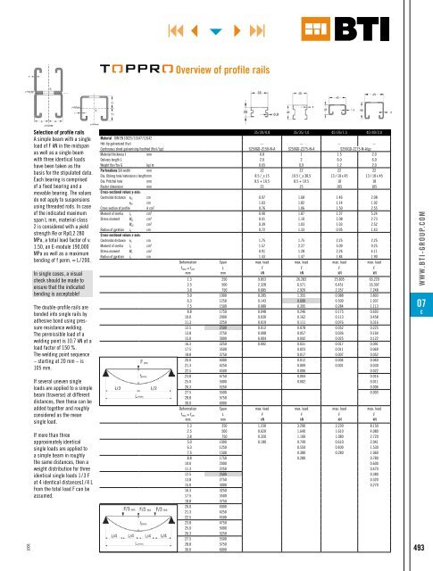
- Page 475 and 476: 1006 Toppro load tables If the rail
- Page 477 and 478: 1006 Load values for Toppro rail co
- Page 479 and 480: 1006 ����� For assembling
- Page 481 and 482: 1006 1) not suitable for stepped th
- Page 483 and 484: 1006 K.+J. Lueg OHG Institut für M
- Page 485 and 486: 1006 dia. 4 mm dia. 10/15 ���
- Page 487 and 488: 1006 13 26 80 117,5 100 150 24 13 3
- Page 489 and 490: 1006 Each set contains two of the s
- Page 491 and 492: 1006 Corresponds to DIN 1988 Final
- Page 493 and 494: 1006 ����� Bath installat
- Page 495: 1006 Empty nameplate, fluted: g The
- Page 499 and 500: 1006 Pipe - dimensions, weights, fi
- Page 501 and 502: 1006 ����� Standard conne
- Page 503 and 504: 1006 ����� with noise-ins
- Page 505 and 506: 1006 ����� Stex quick ass
- Page 507 and 508: 1006 ����� Stex universal
- Page 509 and 510: 1006 ����� U-shackle SX 3
- Page 511 and 512: 1006 ����� C-profile, per
- Page 513 and 514: 1006 Fz Fz Fx Fx ����� St
- Page 515 and 516: 1006 F ����� Angle mount
- Page 517 and 518: 1006 ����� Joint support
- Page 519 and 520: 1006 Spacing bracket E25 Wall brack
- Page 521 and 522: 1006 Attention: Assembly clips for
- Page 523 and 524: 1006 Attention: Assembly clips for
- Page 525 and 526: 1006 A Fixed point Type clip type A
- Page 527 and 528: 1006 ����� Slider GL 37 F
- Page 529 and 530: 1006 ����� Ventilation pi
- Page 531 and 532: 1006 ����� Cold shrink ri
- Page 533 and 534: 1006 ����� Single-handed
- Page 535 and 536: 1006 ����� Hemp coil/hemp
- Page 537 and 538: 1006 ����� Electrical scr
- Page 539 and 540: 1006 g Adjustable in 7 positions (1
- Page 541 and 542: 1006 Extremely stable, robust lifti
- Page 543 and 544: 1006 020983 ����� Gas rad
- Page 545 and 546: 1006 ����� Propane high-p
- Page 547 and 548:
1006 Flat electrodes for universal
- Page 549 and 550:
����� Sealants and PU foa
- Page 551 and 552:
1006 Chemical technical products
- Page 553 and 554:
1006 Adhesives No. Powermont 140 1
- Page 555 and 556:
1006 * Definitions in accordance wi
- Page 557 and 558:
1006 BONDING + SEALING ����
- Page 559 and 560:
1006 BONDING + SEALING ����
- Page 561 and 562:
1006 BONDING + SEALING ����
- Page 563 and 564:
1006 BONDING + SEALING ����
- Page 565 and 566:
1006 BONDING + SEALING ����
- Page 567 and 568:
1006 BONDING + SEALING The details
- Page 569 and 570:
1006 BONDING + SEALING ����
- Page 571 and 572:
1006 CARE + CLEANING ����
- Page 573 and 574:
1006 BONDING + SEALING ����
- Page 575 and 576:
1006 BONDING + SEALING Ring nut C N
- Page 577 and 578:
1006 BONDING + SEALING siliconized
- Page 579 and 580:
1006 BONDING + SEALING Table to est
- Page 581 and 582:
1006 BONDING + SEALING Windows with
- Page 583 and 584:
1006 BONDING + SEALING Depiction of
- Page 585 and 586:
1006 BONDING + SEALING 1 2 1 = seal
- Page 587 and 588:
1006 BONDING + SEALING Verified by
- Page 589 and 590:
1006 � � BONDING + SEALING �
- Page 591 and 592:
1006 BONDING + SEALING ����
- Page 593 and 594:
1006 BONDING + SEALING ����
- Page 595 and 596:
1006 BONDING + SEALING ����
- Page 597 and 598:
1006 BONDING + SEALING ����
- Page 599 and 600:
1006 BONDING + SEALING ����
- Page 601 and 602:
1006 BONDING + SEALING ����
- Page 603 and 604:
1006 BONDING + SEALING ����
- Page 605 and 606:
1006 LUBRICATING + PROTECTING �
- Page 607 and 608:
1006 LUBRICATING + PROTECTING �
- Page 609 and 610:
1006 LUBRICATING + PROTECTING Dvgw*
- Page 611 and 612:
1006 LUBRICATING + PROTECTING Dvgw-
- Page 613 and 614:
1006 PRIMING + PAINTING � ��
- Page 615 and 616:
1006 CARE + CLEANING ����
- Page 617 and 618:
1006 CARE + CLEANING ����
- Page 619 and 620:
1006 CARE + CLEANING ����
- Page 621 and 622:
1006 FIRE PROTECTION ����
- Page 623 and 624:
1006 FIRE PROTECTION ����
- Page 625 and 626:
1006 FIRE PROTECTION ����
- Page 627 and 628:
TOOLS ����� Hand and scre
- Page 629 and 630:
1006 Tools ����� Table of
- Page 631 and 632:
1006 Longitudinal slot 1/4" Phillip
- Page 633 and 634:
1006 Phillips recessed head 1/4" No
- Page 635 and 636:
1006 Diamond coating (DC): For more
- Page 637 and 638:
1006 Pozidriv recessed head Torx (T
- Page 639 and 640:
1006 Yellow slider = Peak PZ Gray s
- Page 641 and 642:
1006 ����� item unit Desi
- Page 643 and 644:
1006 Laser e ����� Screwd
- Page 645 and 646:
1006 Tested Safety �����
- Page 647 and 648:
1006 Tested Safety �����
- Page 649 and 650:
1006 � � � � ����
- Page 651 and 652:
1006 5 mm 6 mm 7 - 8 mm 9 mm 3 - 5
- Page 653 and 654:
1006 A/f A/f 1/2" 3/8" ����
- Page 655 and 656:
1006 ����� Double open-en
- Page 657 and 658:
1006 ����� ring ratchet w
- Page 659 and 660:
1006 For prefiling (rough machining
- Page 661 and 662:
1006 ����� rali ® plane
- Page 663 and 664:
1006 Note: All saws are delivered i
- Page 665 and 666:
1006 Rapid 19 Rapid 11 Rapid 54 Rap
- Page 667 and 668:
1006 ����� Head compressi
- Page 669 and 670:
1006 ����� Coil nailer 7F
- Page 671 and 672:
1006 ����� Compressor Shu
- Page 673 and 674:
1006 ����� Lubricator For
- Page 675 and 676:
1006 Compressed air hose drum 20 m
- Page 677 and 678:
1006 Coupling with external thread
- Page 679 and 680:
1006 ����� ball peen hamm
- Page 681 and 682:
1006 ����� Flat chisel g
- Page 683 and 684:
1006 ����� universal plie
- Page 685 and 686:
1006 ����� Carpenter's pi
- Page 687 and 688:
1006 ����� workshop sciss
- Page 689 and 690:
1006 For figure cuts (also small ra
- Page 691 and 692:
1006 Trapezoid blade 1991 Snap-off
- Page 693 and 694:
1006 ����� Standard spatu
- Page 695 and 696:
1006 ����� Parat tool kit
- Page 697 and 698:
1006 ����� Fix grip quick
- Page 699 and 700:
1006 ����� All-steel scre
- Page 701 and 702:
1006 � � � ����� Cl
- Page 703 and 704:
1006 ����� round loop gS
- Page 705 and 706:
1006 Light metal water level Alumin
- Page 707 and 708:
1006 ����� Steel tape mea
- Page 709 and 710:
1006 � � ����� Plumb-
- Page 711 and 712:
1006 ����� Square for loc
- Page 713 and 714:
1006 ����� winkelfix goni
- Page 715 and 716:
1006 ����� infrared therm
- Page 717 and 718:
1006 ����� Laser Liner pl
- Page 719 and 720:
1006 ����� rotation laser
- Page 721 and 722:
1006 ����� wall holder Fo
- Page 723 and 724:
����� SYSTRA, SAFETY AT W
- Page 725 and 726:
1006 ����� Product lines,
- Page 727 and 728:
1006 ����� The SYSTRA Mod
- Page 729 and 730:
1006 ����� SYSTRA Modul 1
- Page 731 and 732:
1006 ����� SYSTRA Modul 1
- Page 733 and 734:
1006 ����� SYSTRA Modul 1
- Page 735 and 736:
1006 ����� SYSTRA Modul 1
- Page 737 and 738:
1006 ����� SYSTRA Modul 1
- Page 739 and 740:
1006 ����� SYSTRA Modul 1
- Page 741 and 742:
1006 ����� SYSTRA Modul 2
- Page 743 and 744:
1006 ����� SYSTRA Modul 1
- Page 745 and 746:
1006 ����� SYSTRA Modul m
- Page 747 and 748:
1006 ����� Die SYSTRA Mod
- Page 749 and 750:
1006 SYSTRA Modul 4 + toolbag set w
- Page 751 and 752:
1006 Front Back Front Back Front Ba
- Page 753 and 754:
1006 Front Back Front Back Front Ba
- Page 755 and 756:
1006 ����� ����
- Page 757 and 758:
1006 ����� ����
- Page 759 and 760:
1006 ����� ����
- Page 761 and 762:
1006 Front Back Front Back Front Ba
- Page 763 and 764:
1006 SYSTRA Modul mini accessories
- Page 765 and 766:
1006 ����� ����
- Page 767 and 768:
1006 Ball-bearing supported Full ex
- Page 769 and 770:
1006 ����� Insulated shel
- Page 771 and 772:
1006 1006 24 LP hooks short and lon
- Page 773 and 774:
1006 Assembly strip EL3B (with boxe
- Page 775 and 776:
1006 ����� Safe-Tex Prote
- Page 777 and 778:
1006 Skin-friendliness Dermatologic
- Page 779 and 780:
1006 ����� Fine dust mask
- Page 781 and 782:
1006 Work glove glove standard g In
- Page 783 and 784:
1006 Definition of terms Sternal ca
- Page 785 and 786:
1006 � � � � � � �
- Page 787 and 788:
1006 ����� Halogen portab
- Page 789 and 790:
1006 ����� Work light coo
- Page 791 and 792:
1006 Fig. SV 6-16/16 ����
- Page 793 and 794:
F3 WorkWear, ppe ����� F3
- Page 795 and 796:
1006 F3 Workwear, personal protecti
- Page 797 and 798:
1006 You will find additional color
- Page 799 and 800:
1006 We offer an individual labelin
- Page 801 and 802:
1006 ����� ����
- Page 803 and 804:
1006 ����� ����
- Page 805 and 806:
POWER TOOLS ����� Cordles
- Page 807 and 808:
1006 Power tools ����� Ta
- Page 809 and 810:
1006 ����� Cordless screw
- Page 811 and 812:
1006 ����� Cordless impac
- Page 813 and 814:
1006 ����� Cordless jig s
- Page 815 and 816:
1006 ����� Hammer drill B
- Page 817 and 818:
1006 ����� Hammer drill a
- Page 819 and 820:
1006 ����� Drill BTi-Bm 5
- Page 821 and 822:
1006 ����� Diamond core d
- Page 823 and 824:
1006 ����� One-hand angle
- Page 825 and 826:
1006 Overrun brake stops in 2.5 sec
- Page 827 and 828:
1006 ����� Jig saw BTi-ST
- Page 829 and 830:
1006 ����� Planer BTi-H 8
- Page 831 and 832:
1006 ����� Orbital sander
- Page 833 and 834:
1006 ����� Random orbital
- Page 835 and 836:
1006 Attention: Please be careful w
- Page 837 and 838:
1006 Suitable for BTi and makita co
- Page 839 and 840:
VEHICLE FLEET ����� Care
- Page 841 and 842:
1006 Vehicle fleet �����
- Page 843 and 844:
1006 DEKrA-approved �����
- Page 845 and 846:
1006 ����� orange Magic C
- Page 847 and 848:
1006 ����� Stainless stee
- Page 849 and 850:
100 ����� Cleaning cloth
- Page 851 and 852:
1006 ����� Silicone spray
- Page 853 and 854:
1006 ����� Hand lever gre
- Page 855 and 856:
1006 ����� Screw lock Ana
- Page 857 and 858:
1006 ����� pu constructio
- Page 859 and 860:
1006 ����� Zinc spray lig
- Page 861 and 862:
1006 ring ends for cable sections f
- Page 863 and 864:
1006 ����� SYSTrA Modul 1
- Page 865 and 866:
1006 ����� Nylon cable co
- Page 867 and 868:
1006 ����� Marker tag For
- Page 869 and 870:
1006 Rolls 10 m/5 m long ���
- Page 871 and 872:
1006 ����� bit selection
- Page 873 and 874:
1006 ����� Cross handle s
- Page 875 and 876:
1006 ����� Compressor Shu
- Page 877 and 878:
1006 ����� rubber hammer
- Page 879 and 880:
1006 g 7 adjustable settings (10" a
- Page 881 and 882:
1006 ����� one-hand wrenc
- Page 883 and 884:
1006 ����� Contractors bu
- Page 885 and 886:
1006 Index 1K and 2K polyurethane i
- Page 887 and 888:
1006 Cleaning products 772 Clear Vi
- Page 889 and 890:
1006 Diamond sharpening stick 226 D
- Page 891 and 892:
1006 Grip hack saw 659 Ground termi
- Page 893 and 894:
1006 Joint sealing tape VF 300 577
- Page 895 and 896:
1006 Parquet pad 201 Parquet sandin
- Page 897 and 898:
1006 S Saddle flange SX 35 / 35 503
- Page 899 and 900:
1006 Support 150 / 80 / 8 45 as con
- Page 901 and 902:
1006 Thread cutting die 148 Thread
- Page 903 and 904:
1006 ����� 899
- Page 905 and 906:
1006 1006 voices upon receipt and a
- Page 907:
1006 Information ��� In the c