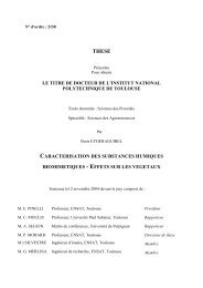
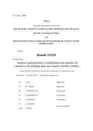
prove that atomization is influenced by several factorscaused by the upstream flow (i.e. in the injector)and operating conditions (P inj , total injectedmass). A good review of these factors has been doneby Reitz and Bracco [26]. The most vivid exampleis the Mokad<strong>de</strong>m vizualisation of the liquid phase inthe combustion chamber [27] (see figure 7). At lowneedle lift, the five issuing jets are different fromone hole to another, whereas at full injection thefive sprays are i<strong>de</strong>ntical.Figure 7: Temporal sequence of the liquid phaseevolution by M ie scattering method on the liquiddroplets. The crank angle is given after the startof injection. P inj = 65 M P a, Inj = 356.6, ρ l = 20kg/m 3 , Q = 40 mm 3 /injection [27].Using Flash radiography, Warken and Krehl [28]have shown that an intact liquid core exists at thenozzle exit. But optical access to the internal structureof the jet is hardly possible, because of theopacity of the jet immediately downstream of thenozzle. It seems more convenient to talk about a<strong>de</strong>nse core. In his experiments, Chaves [7], Badocket al. [29] and Fath et al. [30] have seen gazeousstructures in the core, due to cavitation in the nozzle.V apour bubb<strong>les</strong> disappear rapidly in the <strong>de</strong>nsecore, typically one or two nozzle diameters downstream.This <strong>de</strong>nse region is the one that interestsus with regards to primary breakup. In fact, atomizationneeds a perturbation on the jet surfaceto happen. This perturbation takes place immediatelyat the nozzle exit. The possible causes of theperturbation are listed below.Schweitzer [31] has consi<strong>de</strong>red that the turbulenceof the jet is of primary importance in atomization,and that the aerodynamical interactiononly improves atomization. At the present time, thecontrary is generally admitted since several studiestend to show that turbulence does only give to theliquid jet an irregular surface aspect [32], raising thedrag and consequently the friction due to the ambiantgas. Mac Carthy experiments [33] show thatby increasing L 0 /D 0 ratio (see table 1) and keepingthe same Reynolds and Ohnesorge numbers, atomizationis improved. This is only due to turbulencein the nozzle and shows that this factor tends toimprove atomization.Consi<strong>de</strong>ring that cavitation has a direct effecton atomization is not a good interpretation of theprocess. Paradoxically enough, the collapse of thegazeous structures in the <strong>de</strong>nse spray is a catastrophicprocess [34, 4, 35, 23, 36, 25], but the onlyknown visualization that shows a jet disintegrationdue to a collapsing bubble has been ma<strong>de</strong> by Eifler[8]. The collapse of the bubb<strong>les</strong> (as Winklhofershowed [37]) and the bubble burst at the surface[38] certainly produce surface perturbation, but nodirect atomization is done by this way. The maineffects of cavitation that influence the spray behaviourare rather the raise of the exit velocity dueto the fact that liquid passes through a reduced effectivearea, and the velocity profile perturbationsdue to the transient and intermittent characteristicof cavitation in the nozzle. The attached cavityhas a pseudo-cyclical behaviour, as it can be seenin [39, 40, 41].The velocity perturbations have been studied byChaves et al. [42] in terms of upstream pressurefluctuations. This study is based on the fact thata water-hammer effect is produced due to the needlemovements. Those pressure fluctuations cause atransient behaviour of the spray : as velocity fluctuate,some fast fluid elements can catch up with theslower downstream elements, producing a sort ofsplashing. A bulge is formed,Figure 8: <strong>Diesel</strong>spray structure.P inj = 80M P a ,T ch = 800K,D 0 = 0.2mm.and this is seen in Chaves vizualisations.For the moment, thecauses of the velocity fluctuationsare not clearly un<strong>de</strong>rstood: It can whether be the pressurefluctuations, or whether thecavitation fluctuation that producethose structures. In anycase, those factors are closelyconnected. Bruneaux vizualisationsvoir gil<strong>les</strong> et mieux exploiterla figure. Deman<strong>de</strong>ra son GSM la permissionshow the same type of structuresin engine conditions (see figure8).As atomization is producedby aerodynamical interactions,it seems obvious that the exitjet velocity is the main factorinfluencing the spray behaviour.We can <strong>de</strong>duce fromthe above-mentioned experimentalstudies that the major effectsof the internal flow on the sprayare the velocity fluctuations dueto cavitation and the pressurewaves.
Cavitation mo<strong>de</strong>llingUp-to-date spray mo<strong>de</strong>ls donot take in account the non-stationary conditionsat the nozzle exit, because of the lack of knowledgeof nozzle exit conditions. As experimental investigationsare hardly possible in the injectors, themo<strong>de</strong>lling tool is the solution to know those conditions.Several two-phase mo<strong>de</strong>l types exist, <strong>de</strong>pendingon flow conditions. Floryan and Rasmussen [43]have ma<strong>de</strong> a very good review of the existing mo<strong>de</strong>ls.We have seen the main characteristics of theflow, allowing us to choose the appropriate methods.We have classified the mo<strong>de</strong>ls in two families :the interface tracking and capturing methods, andthe others, i.e. methods that do not take in accountthe interface location.Interface is explicitely <strong>de</strong>fined by the mo<strong>de</strong>l• For interface tracking [44], interface is explicitely<strong>de</strong>fined and advected by the flow. The interface is<strong>de</strong>fined by markers which form a moving boundary,and an interpolation between these points isma<strong>de</strong> to represent the physical boundary. At eachtime step, the information concerning the markers(their location, their sequence) is stored. The advantageof this method is the access to sub-grid sca<strong>les</strong>tructures. But this needs a big storage capacity.The main drawback is the points repartition on theboundary, i.e. several segments can be representedwith a lot of points, whereas others can be verybadly represented. Furthermore, in case of coa<strong>les</strong>cenceor fragmentation, markers must be ad<strong>de</strong>d orremoved. The best way to manage this has not beenfound yet.• Front capturing methods consist in <strong>de</strong>finingexplicitely the interface by a volumic function. Theinterface is not represented but re-built. The mostused is the Volume of Fluid (VOF) method [45, 46,47, 48, 49, 50]. The principle is to represent for eachcell the volumic fraction by a function c(t,x) whichis singular at the interface :c(t,x) = 1 for the phase 1,c(t,x) = 0 for the phase 2.(2)In this method, a set of Navier-Stokes equationsis solved while the <strong>de</strong>nsity of the fluid varies fromliquid to vapour <strong>de</strong>nsities, as following :ρ(t,x) = c(t,x)ρ 1 + (1 − c(t,x))ρ 2 (3)The vapour and the liquid are consi<strong>de</strong>red as incompressible.As we have seen, the interface is re-builtgeometrically. To keep a good accuracy, a lot ofcells are nee<strong>de</strong>d to <strong>de</strong>termine the interface location.Furthermore, Topological changes like coa<strong>les</strong>cenceor fragmentation are hardly performed, exceptwith a very good spatial resolution. Typically,10 cells must be assigned to <strong>de</strong>fine a bubble diameter[51]. Consi<strong>de</strong>ring small bubb<strong>les</strong> whose diameteris approximately 5µm, the 3D computational gridcontains almost 200 million cells for a typical-sizedsingle-holed nozzle. As we have seen that the flowis tridimensional and that we have to compute inthe whole injector, the grid will reach more than 1billion cells for a five-holed injector.• By the same way, the Level Set method [52, 44]consists in <strong>de</strong>fining a continuous and “sufficiently”regular function which is <strong>de</strong>fined as :Φ (t,x) > 0 for the phase 1,Φ (t,x) < 0 for the phase 2,Φ (t,x) = 0 at the interface.The mixture <strong>de</strong>nsity is given by :(4)ρ(Φ ) = ρ g + (ρ l − ρ g )H(Φ ) , (5)with H, Heavisi<strong>de</strong> function, <strong>de</strong>fined as following :⎧⎨ 0 if Φ < 01H(Φ ) =⎩2 if Φ = 01 if Φ > 0(6)Unverdi and Tryggvason [44] have used this methodfor 2D and 3D bubble foam advection. A methodhas been proposed by Smereka [52], in or<strong>de</strong>r tosmooth the Φ discontinuity at the interface. As amatter of fact, this method is hardly usable in caseof great <strong>de</strong>nsity gradients, because of the front diffusion.• The bubble tracking method [51] is an attemptto link the so-called interface tracking mo<strong>de</strong>ls(which may be used for inclusions bigger than thecomputational cells) to the two-fluid mo<strong>de</strong>ls, whichare well adapted to inclusions far smaller than themesh cells. The mo<strong>de</strong>l is a Eulerian-Lagrangianmo<strong>de</strong>l, consi<strong>de</strong>ring liquid as continuous phase. Themajor concept of the method is the ratio d ∗ = d∆x (dis the bubble diameter and ∆ x the computationalcell size). The aim of the mo<strong>de</strong>l is to solve flowdynamics for 0 < d ∗ < 2 and d ∗ > 2. The massand momentum equations are solved for each phase,consi<strong>de</strong>ring no mass transfer. For the continuousliquid phase, slip between the phases, transverselift force and interfacial drag force are not takenin account for d ∗ > 2. The equations for the dispersedvapour phase are written for each bubble,and the bubble shape is <strong>de</strong>termined via graphicalcorrelations <strong>de</strong>pending on three dimension<strong>les</strong>s numbers(Eötvös, Morton and Reynolds numbers) [53].The bubble geometry is used to calculate the voidfraction in each computational cell. This methodis clearly not adapted to <strong>Diesel</strong> engine nozzle flowmo<strong>de</strong>lling, because of the bubble <strong>de</strong>formation dueto the shear stress. Moreover, the equations usedfor each vapour entity are likely to lead to a prohibitivecomputer time. Neverthe<strong>les</strong>s, this method