Modélisation de l'écoulement diphasique dans les injecteurs Diesel
Modélisation de l'écoulement diphasique dans les injecteurs Diesel
Modélisation de l'écoulement diphasique dans les injecteurs Diesel

Create successful ePaper yourself
Turn your PDF publications into a flip-book with our unique Google optimized e-Paper software.
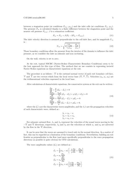
CAV2001:sessionB6.005 5between a stagnation point (at conditions P inj , ρ inj ) and the inlet cells (at conditions P in , ρ in ).The pressure P in is calculated thanks to a finite difference between the stagnation point and thenearest cell pressure P near . β is a relaxation coefficient.P in = P in + β(P 0 − 2P in + P near ) (11)The inlet velocity direction is assumed perpendicular to the cell inlet face, and its magnitu<strong>de</strong> U inis :√ (PinjU in = 2 − P )in(12)ρ inj ρ inThose boundary conditions allow the pressure from the interior of the domain to influence the inletpressure, as we condi<strong>de</strong>r the inlet as subsonic and non cavitating.On the wall, velocity is set to zero.At the exit, typical NSCBC (Navier-Stokes Characteristic Boundary Conditions) seem to bethe best approach for this type of flow. The method that we use consists in expressing inviscidNavier Stokes equations as characteristic equations at the exit.The procedure is as follows : −→ n is the outward normal vector of each exit boundary cell face,−→ τ and−→ b are two vectors which form the local vector base (−→ n ,−→ τ ,−→ b ). Velocities (un , u τ , u b ) arethe tridimensional velocities expressed in the local base.After calculations of characteristic equations, the conservative system at the exit can be written :∂ρ∂t + ρ a (L 4 − L 1 ) = 0∂ρu n+ u nρ∂t a (L 4 − L 1 ) + ρ (L 1 + L 4 ) = 0∂ρu τ+ u τ ρ(13)∂t a (L 4 − L 1 ) + ρL 2 = 0∂ρu b+ u bρ∂t a (L 4 − L 1 ) + ρL 3 = 0,where the L i ’s are the characterisic waves amplitu<strong>de</strong>s, and the λ i ’s are the propagation velocitiesof each characteristic wave, <strong>de</strong>fined as :λ 1 = u n − aλ 2 = λ 3 = u nλ 4 = u n + a.For subsonic outward flow, λ 1 and λ 4 represent the velocities of the sound waves moving in the− −→ n and −→ n directions, respectively. λ 2 and λ 3 are the velocities at which u τ and u b are advectedby the flow in the −→ n direction.It can be seen that the waves are assumed to travel only in the normal direction. As a matter offact, this can be regar<strong>de</strong>d as a limitation of the boundary conditions. Neverthe<strong>les</strong>s, building an exitfrontier as perpendicular to the flow (and more specifically perpendicular to the wave propagationdirection) as possible is quite obvious for CFD calculations.(14)The wave amplitu<strong>de</strong>s values (L i ) are <strong>de</strong>fined as :L 1 = 1 [2 (u n − a) − a ∂ρρ ∂n + ∂u ]n∂n∂u τL 2 = u n∂n∂u bL 3 = u n∂nL 4 = 1 [ a2 (u ∂ρn + a)ρ ∂n + ∂u ]n.∂n(15)