- Page 1:
Arduino Básico
- Page 4 and 5:
Original English language edition p
- Page 6 and 7:
Observação sobre figuras colorida
- Page 8 and 9:
8 Arduino Básico Conectando os com
- Page 10 and 11:
10 Arduino Básico Sistema de núme
- Page 12 and 13:
12 Arduino Básico Digite o código
- Page 14 and 15:
14 Arduino Básico Projeto 43 - Reg
- Page 16 and 17:
Sobre o revisor técnico Josh Adams
- Page 18 and 19:
Introdução Descobri pela primeira
- Page 20 and 21:
capítulo 1 Introdução Desde que
- Page 22 and 23:
22 Arduino Básico Você também ne
- Page 24 and 25:
24 Arduino Básico para permitir su
- Page 26 and 27:
26 Arduino Básico Figura 1.3 - Ins
- Page 28 and 29:
28 Arduino Básico Clique no botão
- Page 30 and 31:
30 Arduino Básico Figura 1.8 - Men
- Page 32 and 33:
32 Arduino Básico Antes de avança
- Page 34 and 35:
34 Arduino Básico O monitor serial
- Page 36 and 37:
36 Arduino Básico Figura 1.18 - Me
- Page 38 and 39:
38 Arduino Básico O último menu,
- Page 40 and 41:
40 Arduino Básico O melhor tipo de
- Page 42 and 43:
42 Arduino Básico serão vitais pa
- Page 44 and 45:
44 Arduino Básico void setup() { p
- Page 46 and 47:
46 Arduino Básico } delay(50); dig
- Page 48 and 49:
48 Arduino Básico Em que V S é a
- Page 50 and 51:
50 Arduino Básico Figura 2.5 - Com
- Page 52 and 53:
52 Arduino Básico Crie um novo ske
- Page 54 and 55:
54 Arduino Básico Repare que a var
- Page 56 and 57:
56 Arduino Básico void loop() { }
- Page 58 and 59:
58 Arduino Básico Digite o código
- Page 60 and 61:
60 Arduino Básico você criou um t
- Page 62 and 63:
62 Arduino Básico A instrução if
- Page 64 and 65:
64 Arduino Básico O loop principal
- Page 66 and 67:
66 Arduino Básico Resistores pull-
- Page 68 and 69:
68 Arduino Básico Caso você alter
- Page 70 and 71:
capítulo 3 Efeitos com LEDs No cap
- Page 72 and 73:
72 Arduino Básico } digitalWrite(l
- Page 74 and 75:
74 Arduino Básico Projeto 6 - Efei
- Page 76 and 77:
76 Arduino Básico Projeto 6 - Efei
- Page 78 and 79:
78 Arduino Básico Figura 3.3 - Cir
- Page 80 and 81:
80 Arduino Básico máximos), o pin
- Page 82 and 83:
82 Arduino Básico void loop() { ra
- Page 84 and 85:
84 Arduino Básico No código, voc
- Page 86 and 87:
86 Arduino Básico Você tem 300 ch
- Page 88 and 89:
88 Arduino Básico Pressione o bot
- Page 90 and 91:
90 Arduino Básico void splitString
- Page 92 and 93:
92 Arduino Básico Serial.begin diz
- Page 94 and 95:
94 Arduino Básico Depois do loop w
- Page 96 and 97:
96 Arduino Básico pode ser vista a
- Page 98 and 99:
98 Arduino Básico } } Serial.print
- Page 100 and 101:
100 Arduino Básico void setLED(cha
- Page 102 and 103:
capítulo 4 Sonorizadores e sensore
- Page 104 and 105: 104 Arduino Básico Projeto 11 - Al
- Page 106 and 107: 106 Arduino Básico O efeito també
- Page 108 and 109: 108 Arduino Básico Projeto 12 - To
- Page 110 and 111: 110 Arduino Básico E dividimos ess
- Page 112 and 113: 112 Arduino Básico Figura 4.3 - Ci
- Page 114 and 115: 114 Arduino Básico Então, você e
- Page 116 and 117: 116 Arduino Básico Digite o códig
- Page 118 and 119: 118 Arduino Básico A voltagem de e
- Page 120 and 121: capítulo 5 Controlando um motor CC
- Page 122 and 123: 122 Arduino Básico Digite o códig
- Page 124 and 125: 124 Arduino Básico Note também qu
- Page 126 and 127: 126 Projeto 16 - Uso do CI controla
- Page 128 and 129: 128 Arduino Básico void loop() { M
- Page 130 and 131: 130 Arduino Básico Figura 5.4 - Po
- Page 132 and 133: 132 Arduino Básico Assuntos e conc
- Page 134 and 135: 134 Arduino Básico Conectando os c
- Page 136 and 137: 136 Arduino Básico Sistema de núm
- Page 138 and 139: 138 Arduino Básico você transfere
- Page 140 and 141: 140 Arduino Básico dados. Depois,
- Page 142 and 143: 142 Arduino Básico Agora, uma inst
- Page 144 and 145: 144 Arduino Básico Deslocamento de
- Page 146 and 147: 146 Arduino Básico O próximo trec
- Page 148 and 149: 148 Arduino Básico Digite o códig
- Page 150 and 151: 150 Arduino Básico EXERCÍCIO Util
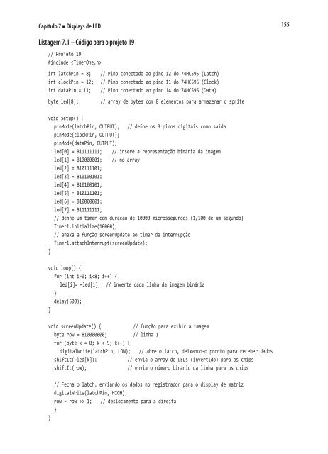
- Page 152 and 153: 152 Arduino Básico 2 CIs registrad
- Page 156 and 157: 156 Arduino Básico void shiftIt(by
- Page 158 and 159: 158 Arduino Básico Isso ocorre por
- Page 160 and 161: 160 Arduino Básico Você está uti
- Page 162 and 163: 162 Arduino Básico Um byte, row,
- Page 164 and 165: 164 Arduino Básico void screenUpda
- Page 166 and 167: 166 Arduino Básico Tabela 7.2 - El
- Page 168 and 169: 168 Arduino Básico Na sequência,
- Page 170 and 171: 170 Arduino Básico Tabela 7.3 - Pi
- Page 172 and 173: 172 Arduino Básico {B00010001, B00
- Page 174 and 175: 174 Arduino Básico } // Envie o bi
- Page 176 and 177: 176 Arduino Básico No extremo asce
- Page 178 and 179: 178 Arduino Básico Por exemplo, co
- Page 180 and 181: 180 Arduino Básico Depois, temos u
- Page 182 and 183: 182 Arduino Básico Agora, você de
- Page 184 and 185: 184 Arduino Básico incrementa a va
- Page 186 and 187: 186 Arduino Básico Para ler esse p
- Page 188 and 189: 188 Arduino Básico void setup() {
- Page 190 and 191: 190 Arduino Básico void loop() { p
- Page 192 and 193: 192 Arduino Básico O comando map r
- Page 194 and 195: 194 Arduino Básico O comando .setR
- Page 196 and 197: capítulo 8 Displays de cristal lí
- Page 198 and 199: 198 Arduino Básico O pino do ajust
- Page 200 and 201: 200 Arduino Básico void scrollRigh
- Page 202 and 203: 202 Arduino Básico A diferença en
- Page 204 and 205:
204 Arduino Básico lcd.print("Scro
- Page 206 and 207:
206 Arduino Básico B01110, B00000,
- Page 208 and 209:
208 Arduino Básico Resistor limita
- Page 210 and 211:
210 Arduino Básico void fahrenheit
- Page 212 and 213:
212 Arduino Básico Esse é um novo
- Page 214 and 215:
214 Arduino Básico lcd.write(B1101
- Page 216 and 217:
capítulo 9 Servomecanismos Neste c
- Page 218 and 219:
218 Arduino Básico Figura 9.3 - Ci
- Page 220 and 221:
220 Arduino Básico Da mesma forma,
- Page 222 and 223:
222 Arduino Básico Figura 9.5 - Ci
- Page 224 and 225:
224 Arduino Básico O servo da esqu
- Page 226 and 227:
226 Arduino Básico A rotina setSer
- Page 228 and 229:
228 Arduino Básico Figura 9.7 - Mo
- Page 230 and 231:
230 Arduino Básico Servo servo2; /
- Page 232 and 233:
capítulo 10 Motores de passo e rob
- Page 234 and 235:
234 Arduino Básico por isso você
- Page 236 and 237:
236 Arduino Básico No loop princip
- Page 238 and 239:
238 Arduino Básico Figura 10.4 - D
- Page 240 and 241:
240 Arduino Básico Para os testes
- Page 242 and 243:
242 Arduino Básico analogWrite(spe
- Page 244 and 245:
244 Arduino Básico digitalWrite(di
- Page 246 and 247:
246 Arduino Básico Shield de motor
- Page 248 and 249:
248 Arduino Básico Figura 10.11 -
- Page 250 and 251:
250 Arduino Básico } rightOffset =
- Page 252 and 253:
252 Arduino Básico vira para a esq
- Page 254 and 255:
254 Arduino Básico pinMode(9, OUTP
- Page 256 and 257:
256 Arduino Básico Você também a
- Page 258 and 259:
258 Arduino Básico Arduino Mega Se
- Page 260 and 261:
260 Arduino Básico pinMode(DATAIN,
- Page 262 and 263:
262 Arduino Básico Esse código te
- Page 264 and 265:
264 Arduino Básico pinMode(SPICLOC
- Page 266 and 267:
266 Arduino Básico Lembre-se de qu
- Page 268 and 269:
268 Arduino Básico Em seguida, tem
- Page 270 and 271:
270 Arduino Básico Depois, você u
- Page 272 and 273:
272 Arduino Básico digitalWrite(SL
- Page 274 and 275:
274 Arduino Básico Mega GLCD Outro
- Page 276 and 277:
276 Arduino Básico pinMode(DATAOUT
- Page 278 and 279:
278 Arduino Básico char spi_transf
- Page 280 and 281:
280 Arduino Básico Há muitos tipo
- Page 282 and 283:
282 Arduino Básico Na sequência,
- Page 284 and 285:
284 Arduino Básico int dotCursor3=
- Page 286 and 287:
capítulo 12 Tela de toque Neste ca
- Page 288 and 289:
288 Arduino Básico Você terá de
- Page 290 and 291:
290 Arduino Básico Projeto 33 - Te
- Page 292 and 293:
292 Arduino Básico Depois de impri
- Page 294 and 295:
294 Arduino Básico Componentes nec
- Page 296 and 297:
296 Arduino Básico Listagem 12.2 -
- Page 298 and 299:
298 Arduino Básico Digite o códig
- Page 300 and 301:
300 Arduino Básico Fazendo isso 16
- Page 302 and 303:
302 Arduino Básico Digite o códig
- Page 304 and 305:
304 Arduino Básico // Pinos RGB #d
- Page 306 and 307:
306 Arduino Básico • o ciclo cor
- Page 308 and 309:
308 Arduino Básico Um potenciômet
- Page 310 and 311:
310 Arduino Básico Você pode remo
- Page 312 and 313:
312 Arduino Básico linha de transm
- Page 314 and 315:
314 Arduino Básico } // inicia a p
- Page 316 and 317:
316 Arduino Básico Agora que você
- Page 318 and 319:
318 Arduino Básico A precisão pod
- Page 320 and 321:
320 Arduino Básico O DS18B20 é um
- Page 322 and 323:
322 Arduino Básico Figura 14.1 - C
- Page 324 and 325:
324 Arduino Básico Na rotina de in
- Page 326 and 327:
326 Projeto 39 - Display ultrassôn
- Page 328 and 329:
328 Arduino Básico Arduino MaxSona
- Page 330 and 331:
330 Arduino Básico displayDigit(cm
- Page 332 and 333:
332 Arduino Básico Por fim, você
- Page 334 and 335:
334 Arduino Básico Componentes nec
- Page 336 and 337:
336 Arduino Básico #define CLK 4 #
- Page 338 and 339:
338 Arduino Básico Então, definim
- Page 340 and 341:
340 Arduino Básico Na sequência,
- Page 342 and 343:
342 Arduino Básico Projeto 41 - Te
- Page 344 and 345:
capítulo 15 Leitura e escrita de d
- Page 346 and 347:
346 Arduino Básico Listagem 15.1 -
- Page 348 and 349:
348 Arduino Básico else { error("f
- Page 350 and 351:
350 Arduino Básico Depois, a funç
- Page 352 and 353:
352 Arduino Básico Primeiramente,
- Page 354 and 355:
354 Arduino Básico if (file.open(&
- Page 356 and 357:
356 Arduino Básico Figura 15.2 - C
- Page 358 and 359:
358 Arduino Básico } Serial.print(
- Page 360 and 361:
360 Arduino Básico } getTemperatur
- Page 362 and 363:
362 Arduino Básico Projeto 43 - Re
- Page 364 and 365:
364 Arduino Básico Em seguida, voc
- Page 366 and 367:
366 Arduino Básico writeString(fil
- Page 368 and 369:
368 Arduino Básico Para iniciar um
- Page 370 and 371:
capítulo 16 Criação de um leitor
- Page 372 and 373:
372 Arduino Básico Digite o códig
- Page 374 and 375:
374 Arduino Básico Componentes nec
- Page 376 and 377:
376 Arduino Básico char* cards[] =
- Page 378 and 379:
378 Arduino Básico 3D00251C27 Card
- Page 380 and 381:
380 Arduino Básico Então, temos u
- Page 382 and 383:
382 Arduino Básico representam sim
- Page 384 and 385:
384 Arduino Básico void unlock() {
- Page 386 and 387:
386 Arduino Básico Figura 17.1 - C
- Page 388 and 389:
388 Arduino Básico client.println(
- Page 390 and 391:
390 Arduino Básico Também definim
- Page 392 and 393:
392 Arduino Básico Então, uma var
- Page 394 and 395:
394 Arduino Básico Então, você e
- Page 396 and 397:
396 Arduino Básico Escolha um tipo
- Page 398 and 399:
398 Arduino Básico byte ip[] = { 1
- Page 400 and 401:
400 Arduino Básico reading_pachube
- Page 402 and 403:
402 Arduino Básico aplicativos do
- Page 404 and 405:
404 Arduino Básico O tempo, em mil
- Page 406 and 407:
406 Arduino Básico Ela inicia info
- Page 408 and 409:
408 Arduino Básico } setupEthernet
- Page 410 and 411:
410 Arduino Básico void loop() { p
- Page 412 and 413:
412 Arduino Básico Client client(s
- Page 414 and 415:
414 Arduino Básico Você pode test
- Page 416 and 417:
416 Arduino Básico Depois, você e
- Page 418 and 419:
418 Arduino Básico E o imprime na
- Page 420 and 421:
420 Projeto 49 - Twitterbot Arduino
- Page 422 and 423:
422 Arduino Básico DeviceAddress o
- Page 424 and 425:
424 Arduino Básico Projeto 49 - Tw
- Page 426 and 427:
426 Arduino Básico Se o status nã
- Page 428 and 429:
428 Arduino Básico tweet(message);
- Page 430 and 431:
430 Arduino Básico } client.printl
- Page 432 and 433:
432 Arduino Básico if (matchTag(""
- Page 434 and 435:
434 Arduino Básico Depois, você c
- Page 436 and 437:
436 Arduino Básico } else { Serial
- Page 438 and 439:
438 Arduino Básico Você adiciona
- Page 440 and 441:
440 Arduino Básico Em seguida, tem
- Page 442 and 443:
442 Arduino Básico Assuntos e conc
- Page 444 and 445:
444 materiais necessários 21 semá
- Page 446 and 447:
446 de matriz de pontos - Pong aná
- Page 448 and 449:
448 RGB 50, 82 tricolores 50 ledSta
- Page 450 and 451:
450 registradores de deslocamento 1
- Page 452 and 453:
452 SPDT, chaves 326 SPI Control Re
- Page 455 and 456:
Conheça também O livro Primeiros