FONIX® 8000 - Frye Electronics
FONIX® 8000 - Frye Electronics
FONIX® 8000 - Frye Electronics

Create successful ePaper yourself
Turn your PDF publications into a flip-book with our unique Google optimized e-Paper software.
Automated Test Sequences 103<br />
3. Use [F8] to save the setting (and all other settings in the Setup Menus) as<br />
default selections. See Sections 2.2.1 and 2.2.4 for details.<br />
4. Press [EXIT] to return to the Opening screen. Your new selection for the<br />
F4-F7 keys should be displayed in the function key list at the bottom of the<br />
screen.<br />
5. Press the function key you selected in Step 2 to enter the ANSI screen.<br />
When inside the ANSI screen, the [EXIT] button is used to leave the screen.<br />
This will take you to the ANSI navigation screen, which contains function keys<br />
selections pointing to all of the available ANSI S3.22 test selections. Use one of<br />
those function keys to enter a different ANSI test screen, or press [EXIT] again<br />
to return to the Opening screen.<br />
5.1.2 Leveling for ANSI<br />
Before you run an ANSI test, you should make sure the sound chamber is leveled.<br />
Even if the screen says that the chamber is leveled, it is a good idea to<br />
periodically re-level it to account for any differences that might have entered<br />
into the testing environment.<br />
The ANSI standard requires that you do a special leveling that accounts for<br />
everything that will be in the chamber during the test. (For most practical office<br />
settings, the leveling procedure explained in Section 3.2 is adequate. If you<br />
are using the 8120 Polar Plot Chamber, you will need to place the 8120 basket<br />
cover over the cavity inside the chamber.<br />
1. Place the dummy microphone (a black cylinder, provided when ANSI<br />
Option is ordered) into the coupler.<br />
2. Attach the hearing aid to the coupler in the way appropriate for the type of<br />
aid under test. See Section 3.3.<br />
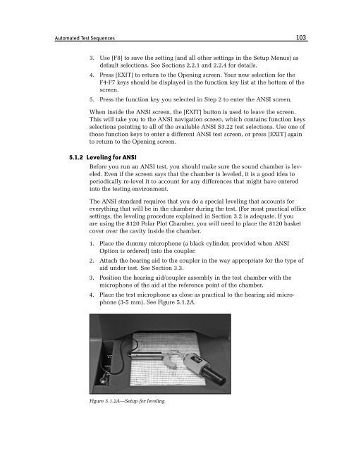
3. Position the hearing aid/coupler assembly in the test chamber with the<br />
microphone of the aid at the reference point of the chamber.<br />
4. Place the test microphone as close as practical to the hearing aid microphone<br />
(3-5 mm). See Figure 5.1.2A.<br />
Figure 5.1.2A—Setup for leveling