FONIX® 8000 - Frye Electronics
FONIX® 8000 - Frye Electronics
FONIX® 8000 - Frye Electronics

Create successful ePaper yourself
Turn your PDF publications into a flip-book with our unique Google optimized e-Paper software.
12 FONIX <strong>8000</strong> Hearing Aid Test System<br />
T630 mAL<br />
ELECTRICAL RATING:<br />
100–240 V~<br />
50-60 Hz .6A<br />
ATTENTION: For service refer to qualified personnel<br />
only. Consult accompanying documents.<br />
FONIX <strong>8000</strong> Serial No. 1234<br />
FONIX ®<br />
<strong>8000</strong><br />
HEARING AID TEST SYSTEM<br />
ELECTRONICS MODULE<br />
Made in Tigard, Oregon, USA<br />
By <strong>Frye</strong> <strong>Electronics</strong>, Inc.<br />
FRYE<br />
<strong>Frye</strong> <strong>Electronics</strong> products are protected by U.S.<br />
and/or foreign patents and/or patents pending<br />
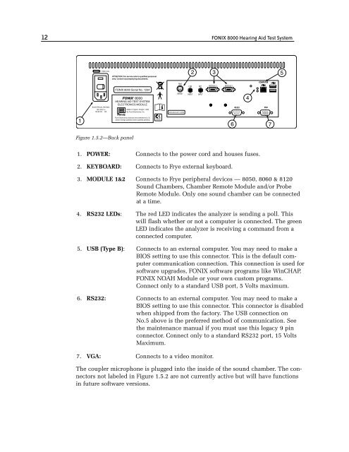
Figure 1.5.2—Back panel<br />
FRYE<br />
KEYBD<br />
LINE<br />
INPUT<br />
MIC<br />
INPUT<br />
MODULE 2 MODULE 1<br />
1. POWER: Connects to the power cord and houses fuses.<br />
2. KEYBOARD: Connects to <strong>Frye</strong> external keyboard.<br />
3. MODULE 1&2 Connects to <strong>Frye</strong> peripheral devices –– 8050, 8060 & 8120<br />
Sound Chambers, Chamber Remote Module and/or Probe<br />
Remote Module. Only one sound chamber can be connected<br />
at a time.<br />
4. RS232 LEDs: The red LED indicates the analyzer is sending a poll. This<br />
will flash whether or not a computer is connected. The green<br />
LED indicates the analyzer is receiving a command from a<br />
connected computer.<br />
5. USB (Type B): Connects to an external computer. You may need to make a<br />
BIOS setting to use this connector. This is the default computer<br />
communication connection. This connection is used for<br />
software upgrades, FONIX software programs like WinCHAP,<br />
FONIX NOAH Module or your own custom programs.<br />
Connect only to a standard USB port, 5 Volts maximum.<br />
6. RS232: Connects to an external computer. You may need to make a<br />
BIOS setting to use this connector. This connector is disabled<br />
when shipped from the factory. The USB connection on<br />
No.5 above is the preferred method of communication. See<br />
the maintenance manual if you must use this legacy 9 pin<br />
connector. Connect only to a standard RS232 port, 15 Volts<br />
Maximum.<br />
7. VGA: Connects to a video monitor.<br />
The coupler microphone is plugged into the inside of the sound chamber. The connectors<br />
not labeled in Figure 1.5.2 are not currently active but will have functions<br />
in future software versions.<br />
RS232<br />
COMPUTER<br />
VGA