FONIX® 8000 - Frye Electronics
FONIX® 8000 - Frye Electronics
FONIX® 8000 - Frye Electronics

Create successful ePaper yourself
Turn your PDF publications into a flip-book with our unique Google optimized e-Paper software.
Coupler Multicurve 75<br />
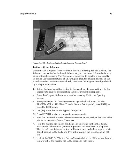
Figure 3.4.10A—Testing with the Sound Chamber Telecoil Board<br />
Testing with the Telewand<br />
When the ANSI Option is ordered with the <strong>8000</strong> Hearing Aid Test System, the<br />
Telewand device is also included. Otherwise, you can order it from the factory<br />
as an optional accessory. The Telewand is supposed to provide a more realistic<br />
test of the telecoil features of a hearing aid than the built-in telecoil in the<br />
sound chamber because it more closely simulates the magnetic field produced<br />
by a telephone receiver.<br />
1. Set up the hearing aid for testing in the usual way by connecting it to the<br />
appropriate coupler and inserting the measurement microphone.<br />
2. Enter the Coupler Multicurve screen by pressing [F1] in the Opening<br />
screen.<br />
3. Press [MENU] in the Coupler screen to open the local menu. Set the<br />
TRANSDUCER to TELEWAND under Source Settings and press [EXIT] to<br />
close the local menu.<br />
4. Use [F5] to set the Source Type to Composite.<br />
5. Press [START] to start a composite measurement.<br />
6. Plug the Telewand into the Telecoil connector on the back of the 8120 Polar<br />
plot or 8050 & 8060 Sound Chambers.<br />
7. Hold the hearing aid in one hand and the Telewand in the other hand.<br />
Position the Telewand as you would position the receiver of a telephone.<br />
That is, hold the Telewand a few millimeters next to the hearing aid, positioned<br />
parallel to the body of a BTE aid or against the faceplate of an ITE<br />
aid.<br />
8. Look at the RMS OUT in the Curve Characteristics box. This shows the current<br />
output of the hearing aid to the magnetic field input.