BY ORDER OF THE SECRETARY OF THE AIR FORCE AIR FORCE ...
BY ORDER OF THE SECRETARY OF THE AIR FORCE AIR FORCE ...
BY ORDER OF THE SECRETARY OF THE AIR FORCE AIR FORCE ...
Create successful ePaper yourself
Turn your PDF publications into a flip-book with our unique Google optimized e-Paper software.
10<br />
AFMAN 11-217V1 3 JANUARY 2005<br />
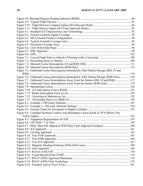
Figure 5.8. Bearing Distance Heading Indicator (BDHI)......................................................................... 80<br />
Figure 5.9. Typical Flight Director.......................................................................................................... 81<br />
Figure 5.10. Flight Director Computer Inputs (ILS Intercept Mode)...................................................... 84<br />
Figure 5.11. Flight Director Inputs (ILS Final Approach Mode). ........................................................... 85<br />
Figure 6.1. Standard ILS Characteristics and Terminology. ................................................................... 92<br />
Figure 6.2. Normal Localizer Signal Coverage. ...................................................................................... 93<br />
Figure 6.3. MLS Ground Facility Configurations. .................................................................................. 94<br />
Figure 6.4. Typical Azimuth Coverage Area........................................................................................... 95<br />
Figure 6.5. Elevation Coverage Area....................................................................................................... 95<br />
Figure 6.6. LDA With Glide Slope.......................................................................................................... 98<br />
Figure 6.7. SDF Approach....................................................................................................................... 99<br />
Figure 6.8. GPS...................................................................................................................................... 102<br />
Figure 7.1. Curved Flight Path as a Result of Homing with a Crosswind............................................. 108<br />
Figure 7.2. Proceeding Direct to Station................................................................................................ 109<br />
Figure 7.3. Inbound Course Interceptions (CI and RMI; HSI).............................................................. 111<br />
Figure 7.4. Inbound Course Interceptions (RMI Only). ........................................................................ 112<br />
Figure 7.5. Outbound Course Interceptions-Immediately After Station Passage (HSI, CI and<br />
RMI)................................................................................................................................................ 114<br />
Figure 7.6. Outbound Course Interceptions-Immediately After Station Passage (RMI Only).............. 116<br />
Figure 7.7. Outbound Course Interceptions-Away From the Station (HSI, CI and RMI)..................... 117<br />
Figure 7.8. Outbound Course Interceptions-Away From the Station (RMI Only)................................ 119<br />
Figure 7.9. Maintaining Course. ............................................................................................................ 120<br />
Figure 7.10. Arc Interception From a Radial......................................................................................... 122<br />
Figure 7.11. Radial Interception From an Arc....................................................................................... 124<br />
Figure 7.12. Correcting to Maintain an Arc........................................................................................... 125<br />
Figure 7.13. Proceeding Direct to a DME Fix...................................................................................... 128<br />
Figure 8.1. Example 1-Off-Scale Altimeter........................................................................................... 141<br />
Figure 8.2. Example 2 - Off-scale Altimeter Settings. .......................................................................... 142<br />
Figure 8.3. Enroute Charts for Navigation in Higher Latitudes. ........................................................... 152<br />
Figure 8.4. Canadian Northern Control Area Boundaries (Areas South of 70°N Where True<br />
Tracks Apply). ................................................................................................................................ 154<br />
Figure 8.5. Equipment Requirements for IAP. ...................................................................................... 158<br />
Figure 8.6. IAP With “/” in Title. .......................................................................................................... 159<br />
Figure 8.7. More Than One Approach With Same Final Approach Guidance...................................... 160<br />
Figure 8.8. ILS Approach. ..................................................................................................................... 161<br />
Figure 8.9. Circling Approach. .............................................................................................................. 162<br />
Figure 8.10. True VOR Approach. ........................................................................................................ 165<br />
Figure 8.11. True NDB Approach. ........................................................................................................ 166<br />
Figure 8.12. True ILS Approach............................................................................................................ 167<br />
Figure 8.13. Magnetic Heading Reference With Grid Course............................................................... 168<br />
Figure 8.14. Grid Approach................................................................................................................... 169<br />
Figure 8.15. Review of the IAP. ............................................................................................................ 170<br />
Figure 8.16. Visual Descent Point (VDP).............................................................................................. 174<br />
Figure 8.17. RNAV (GPS) Approach Minimums. ................................................................................ 176<br />
Figure 8.18. RNAV (GPS) Chart Symbology. ...................................................................................... 178<br />
Figure 8.19. Terminal Arrival Area (TAA). .......................................................................................... 181


