BY ORDER OF THE SECRETARY OF THE AIR FORCE AIR FORCE ...
BY ORDER OF THE SECRETARY OF THE AIR FORCE AIR FORCE ...
BY ORDER OF THE SECRETARY OF THE AIR FORCE AIR FORCE ...

You also want an ePaper? Increase the reach of your titles
YUMPU automatically turns print PDFs into web optimized ePapers that Google loves.
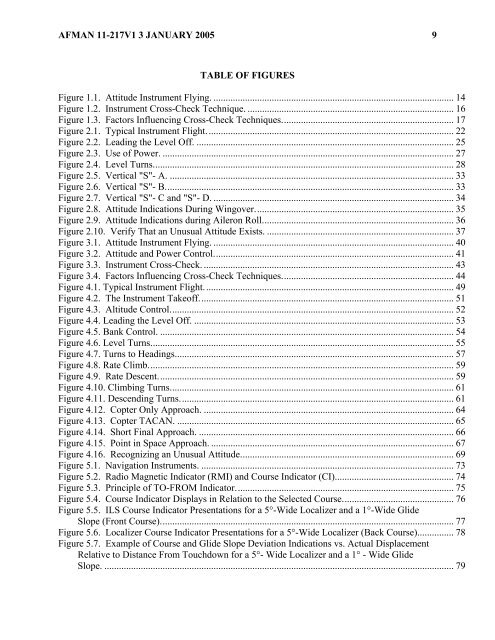
AFMAN 11-217V1 3 JANUARY 2005 9<br />
TABLE <strong>OF</strong> FIGURES<br />
Figure 1.1. Attitude Instrument Flying. ................................................................................................... 14<br />
Figure 1.2. Instrument Cross-Check Technique. ..................................................................................... 16<br />
Figure 1.3. Factors Influencing Cross-Check Techniques....................................................................... 17<br />
Figure 2.1. Typical Instrument Flight...................................................................................................... 22<br />
Figure 2.2. Leading the Level Off. .......................................................................................................... 25<br />
Figure 2.3. Use of Power. ........................................................................................................................ 27<br />
Figure 2.4. Level Turns............................................................................................................................ 28<br />
Figure 2.5. Vertical "S"- A. ..................................................................................................................... 33<br />
Figure 2.6. Vertical "S"- B....................................................................................................................... 33<br />
Figure 2.7. Vertical "S"- C and "S"- D. ................................................................................................... 34<br />
Figure 2.8. Attitude Indications During Wingover.................................................................................. 35<br />
Figure 2.9. Attitude Indications during Aileron Roll............................................................................... 36<br />
Figure 2.10. Verify That an Unusual Attitude Exists. ............................................................................. 37<br />
Figure 3.1. Attitude Instrument Flying. ................................................................................................... 40<br />
Figure 3.2. Attitude and Power Control................................................................................................... 41<br />
Figure 3.3. Instrument Cross-Check. ....................................................................................................... 43<br />
Figure 3.4. Factors Influencing Cross-Check Techniques....................................................................... 44<br />
Figure 4.1. Typical Instrument Flight....................................................................................................... 49<br />
Figure 4.2. The Instrument Takeoff......................................................................................................... 51<br />
Figure 4.3. Altitude Control..................................................................................................................... 52<br />
Figure 4.4. Leading the Level Off. ........................................................................................................... 53<br />
Figure 4.5. Bank Control. ......................................................................................................................... 54<br />
Figure 4.6. Level Turns............................................................................................................................. 55<br />
Figure 4.7. Turns to Headings................................................................................................................... 57<br />
Figure 4.8. Rate Climb.............................................................................................................................. 59<br />
Figure 4.9. Rate Descent.......................................................................................................................... 59<br />
Figure 4.10. Climbing Turns..................................................................................................................... 61<br />
Figure 4.11. Descending Turns................................................................................................................. 61<br />
Figure 4.12. Copter Only Approach. ....................................................................................................... 64<br />
Figure 4.13. Copter TACAN. .................................................................................................................. 65<br />
Figure 4.14. Short Final Approach. ......................................................................................................... 66<br />
Figure 4.15. Point in Space Approach. .................................................................................................... 67<br />
Figure 4.16. Recognizing an Unusual Attitude........................................................................................ 69<br />
Figure 5.1. Navigation Instruments. ........................................................................................................ 73<br />
Figure 5.2. Radio Magnetic Indicator (RMI) and Course Indicator (CI)................................................. 74<br />
Figure 5.3. Principle of TO-FROM Indicator.......................................................................................... 75<br />
Figure 5.4. Course Indicator Displays in Relation to the Selected Course.............................................. 76<br />
Figure 5.5. ILS Course Indicator Presentations for a 5°-Wide Localizer and a 1°-Wide Glide<br />
Slope (Front Course)......................................................................................................................... 77<br />
Figure 5.6. Localizer Course Indicator Presentations for a 5°-Wide Localizer (Back Course)............... 78<br />
Figure 5.7. Example of Course and Glide Slope Deviation Indications vs. Actual Displacement<br />
Relative to Distance From Touchdown for a 5°- Wide Localizer and a 1° - Wide Glide<br />
Slope. ................................................................................................................................................ 79