BY ORDER OF THE SECRETARY OF THE AIR FORCE AIR FORCE ...
BY ORDER OF THE SECRETARY OF THE AIR FORCE AIR FORCE ...
BY ORDER OF THE SECRETARY OF THE AIR FORCE AIR FORCE ...
Create successful ePaper yourself
Turn your PDF publications into a flip-book with our unique Google optimized e-Paper software.
12<br />
AFMAN 11-217V1 3 JANUARY 2005<br />
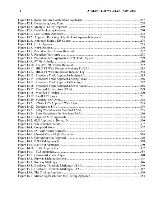
Figure 12.3. Radial and Arc Combination Approach. ........................................................................... 267<br />
Figure 12.4. Determining Lead Point. ................................................................................................... 268<br />
Figure 12.5. Multiple Facility Approach ............................................................................................... 269<br />
Figure 12.6. Dead Reckoning Courses. ................................................................................................. 270<br />
Figure 13.1. Low Altitude Approach..................................................................................................... 272<br />
Figure 13.2. Approach Depicting Only the Final Approach Segment................................................... 273<br />
Figure 13.3. Approach Using a DR Course. .......................................................................................... 274<br />
Figure 13.4. HILO Approach................................................................................................................. 275<br />
Figure 13.5. NoPT Routing.................................................................................................................... 276<br />
Figure 13.6. Procedure Turn Course Reversal....................................................................................... 277<br />
Figure 13.7. Procedure Turn Area. ........................................................................................................ 278<br />
Figure 13.8. Procedure Turn Approach with No FAF Depicted............................................................ 279<br />
Figure 13.9. PT Fix Altitude.................................................................................................................. 280<br />
Figure 13.10. The 45°/180° Course Reversal. ....................................................................................... 282<br />
Figure 13.11. HILO PT With Descent at Holding Fix/FAF. ................................................................. 283<br />
Figure 13.12. HILO PT With Descent on Inbound Leg. ....................................................................... 284<br />
Figure 13.13. Procedure Track Approach (Straight-in)......................................................................... 285<br />
Figure 13.14. Procedure Track Approach (Arcing Final)...................................................................... 286<br />
Figure 13.15. Procedure Track Approach (Teardrop). .......................................................................... 287<br />
Figure 13.16. Procedure Track Approach (Arc to Radial)..................................................................... 288<br />
Figure 13.17. Terminal Arrival Area (TAA). ........................................................................................ 289<br />
Figure 13.18. Modified T Design. ......................................................................................................... 290<br />
Figure 13.19. Parallel T Design. ............................................................................................................ 291<br />
Figure 13.20. Standard TAA Area......................................................................................................... 292<br />
Figure 13.21. RNAV GPS Approach With TAA. ................................................................................. 293<br />
Figure 13.22. Descents in TAA. ............................................................................................................ 294<br />
Figure 13.23. Entry Procedures for Modified TAAs. ............................................................................ 295<br />
Figure 13.24. Entry Procedures for One-Base TAAs. ........................................................................... 296<br />
Figure 14.1. Computed MLS Approach. ................................................................................................ 304<br />
Figure 14.2. MLS Approach at Boise, ID............................................................................................... 306<br />
Figure 14.3. Non-Computed Mode......................................................................................................... 307<br />
Figure 14.4. Computed Mode. ............................................................................................................... 307<br />
Figure 14.5. IAP with Visual Segment. ................................................................................................. 323<br />
Figure 14.6. Charted Visual Flight Procedure. ...................................................................................... 324<br />
Figure 14.7. Converging ILS Approach. ............................................................................................... 326<br />
Figure 14.8. ILS/PRM Approach........................................................................................................... 328<br />
Figure 14.9. ILS/PRM Approach........................................................................................................... 330<br />
Figure 14.10. SOIA Approaches............................................................................................................ 332<br />
Figure 14.11. TLS Approach. ................................................................................................................ 334<br />
Figure 15.1. Downward Vision Angle................................................................................................... 340<br />
Figure 15.2. Runway Lighting Systems................................................................................................. 343<br />
Figure 15.3. Runway Markings. ............................................................................................................ 346<br />
Figure 15.4. Displaced Threshold Markings (USAF)............................................................................ 346<br />
Figure 15.5. Displaced Threshold Markings (FAA).............................................................................. 347<br />
Figure 15.6. The Circling Approach...................................................................................................... 349<br />
Figure 16.1. Missed Approach from the Circling Approach. ................................................................ 354


