Create successful ePaper yourself
Turn your PDF publications into a flip-book with our unique Google optimized e-Paper software.
ED [<strong>DCS</strong> USER MANUAL]<br />
<br />
<br />
<br />
<br />
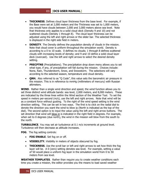
THICKNESS. Defines cloud layer thickness from the base level. For example, if<br />
the Base were set at 2,000 meters and the Thickness was set to 1,000 meters,<br />
you would have clouds between 2,000 and 3,000 meters above sea level. Note<br />
that thickness only applies to a solid cloud deck (Density 9 and 10) and not<br />
scattered clouds (Density 1 through 8). The cloud layer thickness can be<br />
adjusted using the left and right arrows or the slider bar. The selected thickness<br />
is displayed in the right side field in meters.<br />
D<strong>EN</strong>SITY. The Density defines the population density of clouds in the mission.<br />
Note that cloud cover is uniform throughout the simulation world. Density is<br />
according to a 0 to 10 scale. 0 defines no clouds; 1 through 8 defines scattered<br />
clouds with increasing levels of density; and 9 and 10 define a solid cloud layer<br />
deck (overcast). Use the left and right arrows to select the desired density<br />
setting.<br />
PRECPTNS (Precipitations). The precipitation drop down menu allows you to set<br />
what type, if any, of precipitation will fall during the mission. Choices include:<br />
None, Rain, Thunderstorm, Snow, and Snowstorm. The selections will vary<br />
according to the selected season, temperature and cloud density.<br />
QNH. Also referred to as “Q Code”, this value sets the barometric air pressure in<br />
the mission. This is in reference to mmHg (millimeters of mercury) with Russian<br />
altimeters.<br />
WIND. Rather than a single wind direction and speed, the wind function allows you to<br />
set three distinct wind altitude bands: sea level, 2,000 meters, and 8,000 meters. These<br />
are indicated by the three lines within the Wind section of the Weather Tool. To set the<br />
speed in meters per-second (m/s), use the left and right arrows. Note that wind will be<br />
as a constant force without gusting. To the right of the wind speed setting is the wind<br />
direction setting. This can be set in two ways. The first is to click on the radial dial to<br />
denote the direction you want the wind to blow in (North is indicated as the top of the<br />
dial). The second option is to input the value using the left and right arrow buttons. The<br />
set direction that wind will blow in is indicated in the right field in degrees. For example,<br />
when set to 0 degrees (due north), the wind in the mission will blow from the south to<br />
the north.<br />
TURBUL<strong>EN</strong>CE. You may set air turbulence at 0.1 m/s increments at ground level.<br />
Turbulence will then decrease as altitude increases.<br />
FOG. The fog setting controls:<br />
<br />
<br />
<br />
FOG <strong>EN</strong>ABLE. Set fog on or off.<br />
VISIBILITY. Visibility in meters of objects obscured by fog.<br />
THICKNESS. Use the scroll bar or left and right arrows to set how thick the fog<br />
layer will be. A 0 (zero) setting denotes sea level. For example, setting a value<br />
of 50 would place a uniform fog layer in the simulation world from 0 to 50<br />
meters from sea level.<br />
WEATHER TEMPLATES. Rather than require you to create weather conditions each<br />
time you create a mission, the editor provides you the means to load saved weather<br />
74 <strong>DCS</strong> USER MANUAL


