i A PHYSICAL IMPLEMENTATION WITH CUSTOM LOW POWER ...
i A PHYSICAL IMPLEMENTATION WITH CUSTOM LOW POWER ...
i A PHYSICAL IMPLEMENTATION WITH CUSTOM LOW POWER ...

Create successful ePaper yourself
Turn your PDF publications into a flip-book with our unique Google optimized e-Paper software.
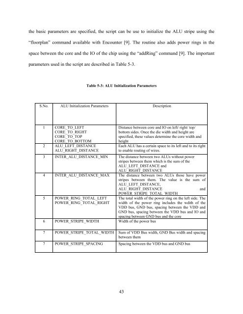
the basic parameters are specified, the script can be use to initialize the ALU stripe using the<br />
“floorplan” command available with Encounter [9]. The routine also adds power rings in the<br />
space between the core and the IO of the chip using the “addRing” command [9]. The important<br />
parameters used in the script are described in Table 5-3.<br />
Table 5-3: ALU Initialization Parameters<br />
S.No. ALU Initialization Parameters Description<br />
1 CORE_TO_LEFT Distance between core and IO on left/ right/ top/<br />
CORE_TO_RIGHT<br />
CORE_TO_TOP<br />
CORE_TO_BOTTOM<br />
2 ALU_LEFT_DISTANCE<br />
ALU_RIGHT_DISTANCE<br />
bottom sides. Once the die width and height are<br />
specified, these values determine the core width and<br />
height<br />
Each ALU has a certain space to its left and to its right<br />
to enable routing of wires.<br />
3 INTER_ALU_DISTANCE_MIN The distance between two ALUs without power<br />
stripes between them which is the sum of the<br />
ALU_LEFT_DISTANCE and<br />
ALU_RIGHT_DISTANCE<br />
4 INTER_ALU_DISTANCE_MAX The distance between two ALUs those have power<br />
stripes between them. The value is the sum of<br />
ALU_LEFT_DISTANCE,<br />
ALU_RIGHT_DISTANCE and<br />
5 <strong>POWER</strong>_RING_TOTAL_LEFT<br />
<strong>POWER</strong>_RING_TOTAL_RIGHT<br />
<strong>POWER</strong>_STRIPE_TOTAL_WIDTH<br />
6 <strong>POWER</strong>_STRIPE_WIDTH Width of the power bus<br />
The total width of the power ring on the left side. The<br />
width of the power ring includes the wdith of the<br />
VDD bus, GND bus, spacing between the VDD and<br />
GND bus, spacing between the VDD bus and IO and<br />
spacing between GND bus and the core<br />
7 <strong>POWER</strong>_STRIPE_TOTAL_WIDTH Sum of VDD Bus width, GND Bus width and spacing<br />
between them<br />
7 <strong>POWER</strong>_STRIPE_SPACING Spacing between the VDD bus and GND bus<br />
43