- Page 1 and 2:
INCH-POUNDDOE STANDARDDOE-STD-1 090
- Page 3:
DISCLAIMERPortions of this document
- Page 7 and 8:
DOE-STD-I090-96 (Rev-I)7.5.6 Attach
- Page 9 and 10:
DOE-STD-I090-96 (Rev-I)9.2.6.3 Hydr
- Page 11 and 12:
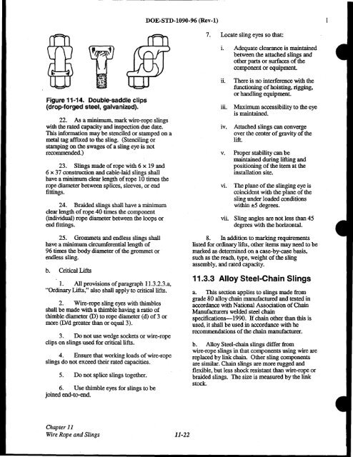
DOE-STD-1090-96 (Rev-l)11.2.3.1 6 x
- Page 13 and 14:
DOE-STD-1090-96 (Rev-l)13.4.5 Disco
- Page 15 and 16:
DOE-STD-I090-96 (Rev-I)15.4.2 Mobil
- Page 18 and 19:
DOE-STD-I090-96 (Rev-I)History and
- Page 20 and 21:
DOE-STD-I090-96 (Rev-I)Acknowledgme
- Page 22 and 23:
DOE-STD-I090-96 (Rev-I)Introduction
- Page 24 and 25:
DOE-STD-I090-96 (Rev-I)CHAPTER 1TER
- Page 26 and 27:
DOE-STD-I090-96 (Rev-I)CLOSING LINE
- Page 28 and 29:
DOE-STD-I090-96 (Rev-I)END CONTROL:
- Page 30 and 31:
LIFT, PREENGINEERED PRODUCTION:Repe
- Page 32 and 33:
QUALIFIED ENGINEER/QUALIFIEDENGINEE
- Page 35 and 36:
DOE-STD-I090-96 (Rev-I)INTENTIONALL
- Page 37 and 38:
-----------------------------------
- Page 39 and 40:
DOE-STD-I090-96 (Rev-I)2.2 CRITICAL
- Page 41 and 42:
DOE-STD-1090-96 (Rev-1)INTENTIONALL
- Page 43 and 44:
DOE-STD-I090-96 (Rev-I)3.2 OPERATIO
- Page 45 and 46:
DOE-STD-I090-96 (Rev-I)2. Perform a
- Page 47 and 48:
DOE-STD-I090-96 (Rev-I)3.4.4 Approv
- Page 49 and 50:
DOE-STD-I090-96 (Rev-I)3.6 TRAINING
- Page 51 and 52:
DOE-STD-I090-96 (Rev-I)INTENTIONALL
- Page 53 and 54:
DOE-STD-I090-96 (Rev-I)that create
- Page 55 and 56:
4.3 OVERHEAD CRANESDOE-STD-I090-96
- Page 57 and 58:
DOE-STD-I090-96 (Rev-I)lNTENTIONAIL
- Page 59 and 60:
DOE-STD-I090-96 (Rev-I)INTENTIONALL
- Page 61 and 62:
DOE-STD-I090-96 (Rev-I)5.2 HOSTILE
- Page 63 and 64:
DOE-STD-1090-96 (Rev-l)EXHIBIT IHOS
- Page 65 and 66:
DOE-STD-I090-96 (Rev-I)INTENTIONALL
- Page 67 and 68:
6.2 QUALIFICATIONDOE-STD-I090-96 (R
- Page 69 and 70:
6.2.5Operators of ForkliftTrucksa.
- Page 71 and 72:
DOE-STD-I090-96 (Rev-I)6.3 TRAINING
- Page 73 and 74:
DOE-STD-1090-96 (Rev-l)24. Records
- Page 75 and 76:
6.4 REQUALIFICATIONDOE-STD-I090-96
- Page 77 and 78:
-----------------------------------
- Page 79 and 80:
-----------------------------------
- Page 81 and 82:
DOE-STD-I090-96 (Rev-!)Gantry Crane
- Page 83 and 84:
DOE-STD-I090-96 (Rev-I)Crane bridge
- Page 85 and 86:
DOE-STD-I090-96 (Rev-I)7.2 INSPECTI
- Page 87 and 88:
DOE-STD-I090-96 (Rev-I)h. Chain-dri
- Page 89 and 90:
DOE-STD-I090-96 (Rev-I)trouble pers
- Page 91 and 92:
DOE-STD-I090-96 (Rev-I)7.4 MAINTENA
- Page 93 and 94:
DOE-STD-I090-96 (Rev-I)HOIST. With
- Page 95 and 96:
DOE-STD-I090-96 (Rev-I)g. Do not lo
- Page 97 and 98:
DOE-STD-1090-96 (Rev-l). IN1ENTIONA
- Page 99 and 100:
DOE-STD-1090-96 (Rev-l)EXHIBIT I (c
- Page 101 and 102:
DOE-STD-I090-96 (Rev-I)EXHIBIT I (c
- Page 103 and 104:
DOE-STD-I090-96 (Rev-I)8.3 TESTING
- Page 105 and 106:
DOE-STD-I090-96 (Rev-I)Figure 8-3.
- Page 107 and 108:
DOE-STD-I090-96 (Rev-I)8.1.1Operato
- Page 109 and 110:
DOE-STD-I090-96 (Rev-I)operating co
- Page 111 and 112:
DOE-STD-I090-96 (Rev-I)8.2 INSPECTI
- Page 113 and 114:
DOE-STD-I090-96 (Rev-I)2. A number
- Page 115 and 116:
DOE-STD-!090-96 (Rev-!)iv.Inspect f
- Page 117 and 118:
DOE-STD-I090-96 (Rev-I)8.4 MAINTENA
- Page 119 and 120:
DOE-STD-I090-96 (Rev-I)d. Do not op
- Page 121 and 122:
DOE-STD-I090-96 (Rev-I)Exhibit I is
- Page 123 and 124:
DOE-STD-I090-96 (Rev-I)EXHIBIT I (c
- Page 125 and 126:
DOE-STD-I090-96 (Rev-I)9.5.29.5.39.
- Page 127 and 128:
DOE-STD-I090-96 (Rev-I)Table 9-1. S
- Page 129 and 130:
DOE-STD-1090-96 (Rev-1)r-1r.ilE3...
- Page 131 and 132:
DOE-STD-I090-96 (Rev-I)9.2 INSPECTI
- Page 133 and 134:
DOE-STD-I090-96 (Rev-I)d. Evidence
- Page 135 and 136:
DOE-STD-I090-96 (Rev-I)before retur
- Page 137 and 138:
DOE-STD-I090-96 (Rev-I)9.4 MAINTENA
- Page 139 and 140:
DOE-STD-I090-96 (Rev-!)t. Lock carr
- Page 141 and 142:
DOE-STD-I090-96 (Rev-I)Figure 9-2.
- Page 143 and 144:
DOE-STD-1090-96 (Rev-1)c. Durable s
- Page 145 and 146:
DOE-STD-I090-96 (Rev-I)1. Cranel10a
- Page 147 and 148: DOE-STD-I090-96 (Rev-I)IIIIIIIIIIII
- Page 149 and 150: DOE·STD·I090·96 (Rev-I)HOIST. Wi
- Page 151 and 152: DOE-STD-I090-96 (Rev-I)RETRACT 800M
- Page 153 and 154: DOE-STD-I090-96 (Rev-I)Exhibit I is
- Page 155 and 156: DOE-STD-I090-96 (Rev-I)EXHIBIT I (c
- Page 157 and 158: DOE-STD-I090-96 (Rev-I)EXHIBIT I (c
- Page 159 and 160: DOE-STD-1090-96 (Rev-1)10.5.5 Movin
- Page 161 and 162: DOE-STD-I090-96 (Rev-I)10.1.6 Modif
- Page 163 and 164: DOE-STD-I090-96 (Rev-I)1. Class I-l
- Page 165 and 166: DOE-STD-I090-96 (Rev-I)CAUTIONONLY
- Page 167 and 168: -- ----------------------------10.4
- Page 169 and 170: DOE-STD-1090-96 (Rev-l)20. To avoid
- Page 171 and 172: DOE-STD-1090-96 (Rev-1)RAISE THE TI
- Page 173 and 174: -- -----------DOE-STD-I090-96 (Rev-
- Page 175 and 176: DOE-STD-I090-96 (Rev-I)EXHIBIT I (c
- Page 177 and 178: DOE-STD-I090-96 (Rev-I)INTENTIONALL
- Page 179 and 180: DOE-STD-1090-96 (Rev-l)Table 11-1.
- Page 181 and 182: DOE-STD-I090-96 (Rev-I)11.2 WIRE RO
- Page 183 and 184: -~ --~---------------------------DO
- Page 185 and 186: DOE-STD-I090-96 (Rev-I)11.3 SLINGS1
- Page 187 and 188: DOE-STD-1090-96 (Rev-1)11.3.1.3 Des
- Page 189 and 190: DOE-STD-I090-96 (Rev-I)Table 11-4.
- Page 191 and 192: DOE-STD-I090-96 (Rev-I)Table 11-6.
- Page 193 and 194: DOE-STD-1090-96 (Rev-l)Table 11-8.
- Page 195 and 196: DOE-STD-I090-96 (Rev-I)Angle of cho
- Page 197: DOE-STD-I090-96 (Rev-I)temperatures
- Page 201 and 202: -------------------DOE-STD-I090-96
- Page 203 and 204: -_.._-----~------------DOE-STD-I090
- Page 205 and 206: DOE-STD-I090-96 (Rev-I)Table 11-13.
- Page 207 and 208: DOE·STD·I090·96 (Rev-I)q. Never
- Page 209 and 210: DOE-STD-I090-96 (Rev-I)j. Despite t
- Page 211 and 212: DOE-STD-I090-96 (Rev-I)Table 11-14.
- Page 213 and 214: DOE·STD·1090-96 (Rev-1)certificat
- Page 215 and 216: DOE-STD-I090-96 (Rev-I)Exhibits I t
- Page 217 and 218: DOE-STD-1090-96 (Rev-l)lNTENTIONALL
- Page 219 and 220: ------DOE-STD-I090-96 (Rev-I)EXHIBI
- Page 221 and 222: DOE-STD-I090-96 (Rev-I)INTENTIONALL
- Page 223 and 224: DOE-STD-1090-96 (Rev-l)INTENTIONALL
- Page 225 and 226: -----------------------------------
- Page 227 and 228: DOE-STD-I090-96 (Rev-I)Good and Bad
- Page 229 and 230: 12.2 RIGGING HOOKSDOE-STD-I090-96 (
- Page 231 and 232: DOE-STD-I090-96 (Rev-I)2. Heavy ser
- Page 233 and 234: DOE-STD-I090-96 (Rev-I)Typical shac
- Page 235 and 236: DOE-STD-I090-96 (Rev-I)• Shoulder
- Page 237 and 238: 12.5 TURNBUCKLESDOE-STD-I090-96 (Re
- Page 239 and 240: 12.6 LINKS AND RINGSDOE-STD-I090-96
- Page 241 and 242: DOE-STD-I090-96 (Rev-I)12.7 METAL-P
- Page 243 and 244: DOE-STD-I090-96 (Rev-I)Exhibit I is
- Page 245 and 246: ---------------------------DOE-STD-
- Page 247 and 248: DOE-STD-I090-96 (Rev-I)INTENTIONALL
- Page 249 and 250:
DOE-STD-1090-96 (Rev-l)13.2 INSPECT
- Page 251 and 252:
DOE-STD-I090-96 (Rev-I)13.3 TESTING
- Page 253 and 254:
DOE-STD-1090-96 (Rev-l)13.4 NONDEST
- Page 255 and 256:
-------------------------------~--1
- Page 257 and 258:
-----------------------------------
- Page 259 and 260:
DOE-STD-1090-96 (Rev-1)14.4.4.3 Per
- Page 261 and 262:
DOE-STD-I090-96 (Rev-I)14.2 STRUCTU
- Page 263 and 264:
.----------------------------------
- Page 265 and 266:
DOE-STD-I090-96 (Rev-I)14.2.7 Maint
- Page 267 and 268:
DOE-STD-I090-96 (Rev-!)Four-pad pow
- Page 269 and 270:
DOE-STD-I090-96 (Rev-I)14.3.5 Testi
- Page 271 and 272:
DOE-STD-I090-96 (Rev-I)14.4 MAGNETS
- Page 273 and 274:
DOE-STD-I090-96 (Rev-I)1. External
- Page 275 and 276:
DOE-STD-I090-96 (Rev-I)instructed b
- Page 277 and 278:
- ---------------------------------
- Page 279 and 280:
DOE-STD-I090-96 (Rev-I)6. Charging
- Page 281 and 282:
DOE-STD-!090-96 (Rev-!)EXHIBIT IPag
- Page 283 and 284:
-------------------~---------------
- Page 285 and 286:
DOE·STD·I090-96 (Rev-I)15.2 DEFIN
- Page 287 and 288:
General note for Figures 15-5 throu
- Page 289 and 290:
DOE-STD-I090-96 (Rev-I)LIFT, ORDINA
- Page 291 and 292:
DOE-STD-1090~96 (Rev-l)Consideratio
- Page 293 and 294:
DOE-STD-I090-96 (Rev-I)15.4.2.4 Fre
- Page 295 and 296:
DOE-STD-I090-96 (Rev-I)4. Corroded
- Page 297 and 298:
DOE-STD-I090-96 (Rev-I)attention to
- Page 299 and 300:
DOE-STD-I090-96 (Rev-I)b. Test load
- Page 301 and 302:
DOE-STD-!090-96 (Rev-!)regardless Q
- Page 303 and 304:
DOE-STD-1090-96 (Rev-1)EMERGENCY ST
- Page 305 and 306:
DOE-STD-I090-96 (Rev-I)so by an app
- Page 307 and 308:
DOE-STD-I090-96 (Rev-I)Figure 15-13
- Page 309 and 310:
DOE-STD-I090-96 (Rev-I)Figure 15-14
- Page 311 and 312:
DOE-STD-I090-96 (Rev-I)Figure 15-15
- Page 313 and 314:
DOE-STD-I090-96 (Rev-I)include the
- Page 315 and 316:
DOE-STD-1090-96 (Rev-l)the platform
- Page 317 and 318:
DOE-STD-I090-96 (Rev-I)h. Report an
- Page 319 and 320:
DOE-STD-!090-96 (Rev-!)fRAISE THE T
- Page 321 and 322:
DOE-STD-I090-96 (Rev-I)h. Provide 4
- Page 323 and 324:
DOE-STD-1090-96 (Rev-l)ASME B56.7,
- Page 325 and 326:
DOE-STD-I090-96 (Rev-I)INTENTIONALL