Datascope - Mindray
Datascope - Mindray
Datascope - Mindray

You also want an ePaper? Increase the reach of your titles
YUMPU automatically turns print PDFs into web optimized ePapers that Google loves.
3 - 4 0070-10-0683 AS3000 Service Manual<br />
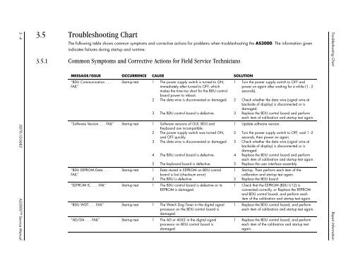
3.5 Troubleshooting Chart<br />
The following table shows common symptoms and corrective actions for problems when troubleshooting the AS3000. The information given<br />
indicates failures during startup and runtime.<br />
3.5.1 Common Symptoms and Corrective Actions for Field Service Technicians<br />
MESSAGE/ISSUE OCCURRENCE CAUSE SOLUTION<br />
“BDU Communication . . .<br />
FAIL”<br />
Startup test 1 The power supply switch is turned to ON,<br />
immediately after turned to OFF, which<br />
makes the time too short for the BDU control<br />
board power to reboot.<br />
2 The data wire is disconnected or damaged.<br />
3 The BDU control board is defective.<br />
“Software Version . . . FAIL” Startup test 1 Software versions of GUI, BDU and<br />
Keyboard are incompatible.<br />
2 The power supply switch was turned ON,<br />
and OFF quickly.<br />
3 The data wire is disconnected or damaged.<br />
“BDU EEPROM Data . . .<br />
FAIL”<br />
4 The BDU control board is defective.<br />
5 The keyboard board is defective.<br />
Startup test 1 Data stored in EEPROM on BDU control<br />
board is lost (checksum error)<br />
2 The BDU is defective<br />
“EEPROM IC . . . FAIL” Startup test 1 The BDU control board is defective or its<br />
EEPROM is damaged.<br />
“BDU WDT . . . FAIL” Startup test 1 The Watch Dog Timer in the digital signal<br />
processor on the BDU control board is<br />
damaged.<br />
“AD/DA . . . FAIL” Startup test 1 The AD or 4052 in the digital signal<br />
processor on BDU control board is<br />
damaged.<br />
1 Turn the power supply switch to OFF and<br />
power on again after waiting for a while (1 - 2<br />
seconds).<br />
2 Check whether the data wire (signal wire at<br />
backside of display) is disconnected or is<br />
damaged.<br />
3 Replace the BDU control board and perform<br />
each item of calibration and startup test again.<br />
1 Update software version.<br />
2 Turn the power supply switch to OFF, wait 1 -2<br />
seconds, then power on again.<br />
3 Check whether the data wire (signal wire at<br />
backside of display) is disconnected or is<br />
damaged.<br />
4 Replace the BDU control board and perform<br />
each item of calibration and startup test again.<br />
5 Replace the user interface assembly.<br />
1 Startup. Then perform each item of the<br />
calibration and startup test again.<br />
2 Replace the BDU board<br />
1 Check that the EEPROM (BDU U12) is<br />
connected correctly, or Replace the EEPROM<br />
and BDU control board, and perform each<br />
item of the calibration and startup test again.<br />
1 Replace the BDU control board, and perform<br />
each item of calibration and startup test again.<br />
1 Replace the BDU control board, and perform<br />
each item of the calibration and startup test<br />
again.<br />
Troubleshooting Chart Repair Information