Datascope - Mindray
Datascope - Mindray
Datascope - Mindray

You also want an ePaper? Increase the reach of your titles
YUMPU automatically turns print PDFs into web optimized ePapers that Google loves.
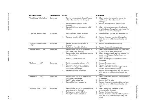
AS3000 Service Manual 0070-10-0683 3 - 5<br />
MESSAGE/ISSUE OCCURRENCE CAUSE SOLUTION<br />
“Vent/Manual Valve Failure” Startup test 1 The wire that connects to the vent/manual<br />
valve is disconnected or is damaged.<br />
2 The vent/manual solenoid valve is<br />
damaged.<br />
3 The amplifier board or connection cable<br />
defective.<br />
“Expiration Sensor Failure” Startup test 1 Fresh gas flow is present at startup.<br />
“Keyboard Communication .<br />
. . FAIL”<br />
2 The sensor board is defective.<br />
Startup test 1 The data wire is disconnected or is<br />
damaged.<br />
2 The keyboard board is defective.<br />
“Pressure Sensor . . . FAIL” Startup test 1 The connection wire of the PAW board is<br />
disconnected or is damaged.<br />
2 The connection of the PAW board or sensor<br />
board is defective.<br />
3 The tubing kinked or occluded.<br />
“O 2 Sensor . . . FAIL” Startup test 1 The O 2 concentration is below 16%.<br />
2 The oxygen sensor is out of range.<br />
3 The main unit-oxygen sensor cable is<br />
disconnected or damaged.<br />
4 The amplifier board is defective.<br />
“PEEP Valve . . . FAIL” Startup test 1 The connection wire of the PEEP valve is<br />
disconnected or damaged.<br />
2 The PEEP valve is defective.<br />
3 The Amplifier board is defective.<br />
“Inspiration Valve . . . FAIL” Startup test 1 The connection wire of the inspiration valve<br />
is disconnected or damaged.<br />
2 The inspiration valve is defective.<br />
3 The amplifier board is defective.<br />
1 Check whether the connection wire of the<br />
vent/manual valve is disconnected or is<br />
damaged.<br />
2 Replace the vent/manual solenoid valve.<br />
3 Check the connection cable and replace the<br />
amplifier board. Then perform each item of the<br />
calibration and startup tests again.<br />
1 Turn off all fresh gas flow and reboot the unit.<br />
2 Replace the sensor board, and then perform<br />
each item of the calibration and startup test<br />
again.<br />
1 Replace the user interface assembly.<br />
2 Replace the user interface assembly.<br />
1 Check whether the connection wire of the PAW<br />
board is disconnected or damaged.<br />
2 Check the power supply and connection of the<br />
sensor board. Replace the Paw board and<br />
sensor board.<br />
3 Check the tubing for kinks and remove any<br />
occlusions.<br />
1 Increase O2 concentration.<br />
2 Replace the oxygen sensor.<br />
3 Check whether the main unit-oxygen sensor<br />
cable is disconnected or damaged.<br />
4 Replace the amplifier board, and then perform<br />
each item of the calibration and startup test<br />
again.<br />
1 Check whether the PEEP valve is disconnected<br />
or damaged.<br />
2 Replace the PEEP valve.<br />
3 Replace the amplifier board and then perform<br />
each item of the calibration and startup test<br />
again.<br />
1 Check whether the inspiration valve is<br />
disconnected or damaged.<br />
2 Replace the inspiration valve.<br />
3 Replace the amplifier board and then perform<br />
each item of the calibration and startup test<br />
again.<br />
Repair Information Troubleshooting Chart