2Gb: x4, x8, x16 DDR3 SDRAM - Micron
2Gb: x4, x8, x16 DDR3 SDRAM - Micron
2Gb: x4, x8, x16 DDR3 SDRAM - Micron
You also want an ePaper? Increase the reach of your titles
YUMPU automatically turns print PDFs into web optimized ePapers that Google loves.
<strong>2Gb</strong>: <strong>x4</strong>, <strong>x8</strong>, <strong>x16</strong> <strong>DDR3</strong> <strong>SDRAM</strong><br />
Features<br />
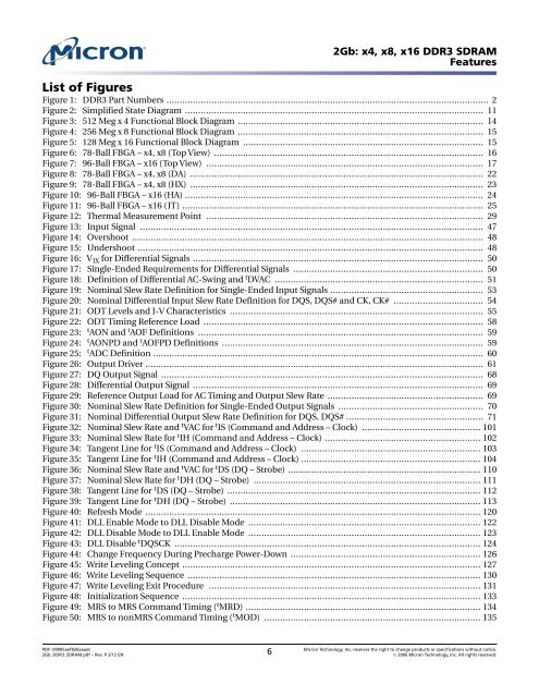
List of Figures<br />
Figure 1: <strong>DDR3</strong> Part Numbers .......................................................................................................................... 2<br />
Figure 2: Simplified State Diagram ................................................................................................................. 11<br />
Figure 3: 512 Meg x 4 Functional Block Diagram ............................................................................................. 14<br />
Figure 4: 256 Meg x 8 Functional Block Diagram ............................................................................................. 15<br />
Figure 5: 128 Meg x 16 Functional Block Diagram ........................................................................................... 15<br />
Figure 6: 78-Ball FBGA – <strong>x4</strong>, <strong>x8</strong> (Top View) ...................................................................................................... 16<br />
Figure 7: 96-Ball FBGA – <strong>x16</strong> (Top View) ......................................................................................................... 17<br />
Figure 8: 78-Ball FBGA – <strong>x4</strong>, <strong>x8</strong> (DA) ............................................................................................................... 22<br />
Figure 9: 78-Ball FBGA – <strong>x4</strong>, <strong>x8</strong> (HX) ............................................................................................................... 23<br />
Figure 10: 96-Ball FBGA – <strong>x16</strong> (HA) ................................................................................................................. 24<br />
Figure 11: 96-Ball FBGA – <strong>x16</strong> (JT) .................................................................................................................. 25<br />
Figure 12: Thermal Measurement Point ......................................................................................................... 29<br />
Figure 13: Input Signal .................................................................................................................................. 47<br />
Figure 14: Overshoot ..................................................................................................................................... 48<br />
Figure 15: Undershoot ................................................................................................................................... 48<br />
Figure 16: V IX for Differential Signals .............................................................................................................. 50<br />
Figure 17: Single-Ended Requirements for Differential Signals ........................................................................ 50<br />
Figure 18: Definition of Differential AC-Swing and t DVAC ............................................................................... 51<br />
Figure 19: Nominal Slew Rate Definition for Single-Ended Input Signals .......................................................... 53<br />
Figure 20: Nominal Differential Input Slew Rate Definition for DQS, DQS# and CK, CK# .................................. 54<br />
Figure 21: ODT Levels and I-V Characteristics ................................................................................................ 55<br />
Figure 22: ODT Timing Reference Load .......................................................................................................... 58<br />
Figure 23: t AON and t AOF Definitions ............................................................................................................ 59<br />
Figure 24: t AONPD and t AOFPD Definitions ................................................................................................... 59<br />
Figure 25: t ADC Definition ............................................................................................................................. 60<br />
Figure 26: Output Driver ................................................................................................................................ 61<br />
Figure 27: DQ Output Signal .......................................................................................................................... 68<br />
Figure 28: Differential Output Signal .............................................................................................................. 69<br />
Figure 29: Reference Output Load for AC Timing and Output Slew Rate ........................................................... 69<br />
Figure 30: Nominal Slew Rate Definition for Single-Ended Output Signals ....................................................... 70<br />
Figure 31: Nominal Differential Output Slew Rate Definition for DQS, DQS# .................................................... 71<br />
Figure 32: Nominal Slew Rate and t VAC for t IS (Command and Address – Clock) ............................................. 101<br />
Figure 33: Nominal Slew Rate for t IH (Command and Address – Clock) ........................................................... 102<br />
Figure 34: Tangent Line for t IS (Command and Address – Clock) .................................................................... 103<br />
Figure 35: Tangent Line for t IH (Command and Address – Clock) .................................................................... 104<br />
Figure 36: Nominal Slew Rate and t VAC for t DS (DQ – Strobe) ......................................................................... 110<br />
Figure 37: Nominal Slew Rate for t DH (DQ – Strobe) ...................................................................................... 111<br />
Figure 38: Tangent Line for t DS (DQ – Strobe) ................................................................................................ 112<br />
Figure 39: Tangent Line for t DH (DQ – Strobe) ............................................................................................... 113<br />
Figure 40: Refresh Mode ............................................................................................................................... 120<br />
Figure 41: DLL Enable Mode to DLL Disable Mode ........................................................................................ 122<br />
Figure 42: DLL Disable Mode to DLL Enable Mode ........................................................................................ 123<br />
Figure 43: DLL Disable t DQSCK .................................................................................................................... 124<br />
Figure 44: Change Frequency During Precharge Power-Down ........................................................................ 126<br />
Figure 45: Write Leveling Concept ................................................................................................................. 127<br />
Figure 46: Write Leveling Sequence ............................................................................................................... 130<br />
Figure 47: Write Leveling Exit Procedure ....................................................................................................... 131<br />
Figure 48: Initialization Sequence ................................................................................................................. 133<br />
Figure 49: MRS to MRS Command Timing ( t MRD) ......................................................................................... 134<br />
Figure 50: MRS to nonMRS Command Timing ( t MOD) .................................................................................. 135<br />
PDF: 09005aef826aaadc<br />
<strong>2Gb</strong>_<strong>DDR3</strong>_<strong>SDRAM</strong>.pdf – Rev. P 2/12 EN 6 <strong>Micron</strong> Technology, Inc. reserves the right to change products or specifications without notice.<br />
� 2006 <strong>Micron</strong> Technology, Inc. All rights reserved.


