Airborne Gravity 2010 - Geoscience Australia
Airborne Gravity 2010 - Geoscience Australia
Airborne Gravity 2010 - Geoscience Australia

You also want an ePaper? Increase the reach of your titles
YUMPU automatically turns print PDFs into web optimized ePapers that Google loves.
<strong>Airborne</strong> <strong>Gravity</strong> <strong>2010</strong><br />
Even in the laboratory, Super conducting Quantum Interference Devices (SQuIDs), operating at liquid<br />
helium temperatures, are required to measure the extremely small rotational movement of the bars. In<br />
the “hostile” airborne environment, movement of the bars will be influenced by normal translational (i.e.<br />
up/down, side to side) and rotational (roll, yaw and pitch) motion of the aircraft. These effects are<br />
minimised by precise balancing of the bars and active rotational stabilisation.<br />
Some details of the VK1 instrument were released at the ASEG conference in Adelaide, in February<br />
2009 (Anstie et al., 2009). At that time, the instrument had been partially assembled and had<br />
demonstrated a measurement of gravity gradient, in the laboratory, with only partial rotational<br />
stabilisation. This paper reports on progress since that date in preparation for flight testing.<br />
State of preparations for flight testing<br />
The “near flight ready” instrument has measured gravity gradients in the laboratory, both with and<br />
without the active stabilisation in operation.<br />
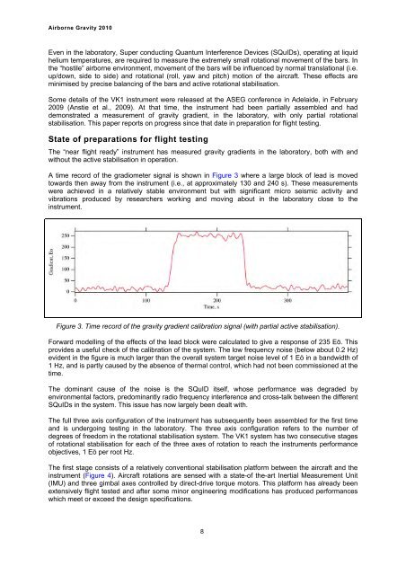
A time record of the gradiometer signal is shown in Figure 3 where a large block of lead is moved<br />
towards then away from the instrument (i.e., at approximately 130 and 240 s). These measurements<br />
were achieved in a relatively stable environment but with significant micro seismic activity and<br />
vibrations produced by researchers working and moving about in the laboratory close to the<br />
instrument.<br />
Figure 3. Time record of the gravity gradient calibration signal (with partial active stabilisation).<br />
Forward modelling of the effects of the lead block were calculated to give a response of 235 Eö. This<br />
provides a useful check of the calibration of the system. The low frequency noise (below about 0.2 Hz)<br />
evident in the figure is much larger than the overall system target noise level of 1 Eö in a bandwidth of<br />
1 Hz, and is partly caused by the absence of thermal control, which had not been commissioned at the<br />
time.<br />
The dominant cause of the noise is the SQuID itself, whose performance was degraded by<br />
environmental factors, predominantly radio frequency interference and cross-talk between the different<br />
SQuIDs in the system. This issue has now largely been dealt with.<br />
The full three axis configuration of the instrument has subsequently been assembled for the first time<br />
and is undergoing testing in the laboratory. The three axis configuration refers to the number of<br />
degrees of freedom in the rotational stabilisation system. The VK1 system has two consecutive stages<br />
of rotational stabilisation for each of the three axes of rotation to reach the instruments performance<br />
objectives, 1 Eö per root Hz.<br />
The first stage consists of a relatively conventional stabilisation platform between the aircraft and the<br />
instrument (Figure 4). Aircraft rotations are sensed with a state-of the-art Inertial Measurement Unit<br />
(IMU) and three gimbal axes controlled by direct-drive torque motors. This platform has already been<br />
extensively flight tested and after some minor engineering modifications has produced performances<br />
which meet or exceed the design specifications.<br />
8