Airborne Gravity 2010 - Geoscience Australia
Airborne Gravity 2010 - Geoscience Australia
Airborne Gravity 2010 - Geoscience Australia
You also want an ePaper? Increase the reach of your titles
YUMPU automatically turns print PDFs into web optimized ePapers that Google loves.
<strong>Airborne</strong> <strong>Gravity</strong> <strong>2010</strong><br />
Abstract<br />
The advantages of the full tensor over Gz<br />
Wayne Stasinowsky 1<br />
1 Pitney Bowes Business Insight (formerly Encom Technology)<br />
(wayne.stasinowsky@encom.com.au)<br />
Use of the full gravity tensor provides advantages over the vertical component (Gz) in a number of<br />
situations. Small discrete bodies such as kimberlite pipes can be directly interpreted in their correct<br />
location even if they occur between survey lines. Interpretation of these and other bodies do not<br />
require prior gridding and can be inverted without first levelling the data, thereby providing significant<br />
advantages in areas with rugged terrain. Inversions are also more robust in the presence of noise and<br />
need fewer points over the anomaly to obtain a solution.<br />
While the tensor can be obtained from filtering a grid of any single component, the advantages are<br />
greatest when using a directly measured tensor rather than one derived from a grid of Gz. Derived<br />
tensors reflect the information content of the source component, and can induce artefacts in the<br />
interpretation such as errors in position and depth of the source.<br />
Examples of the advantages of the tensor over Gz are demonstrated through forward models and joint<br />
inversion of synthetic multi-channel tensor data.<br />
What is a Tensor?<br />
Potential fields such as <strong>Gravity</strong> are vector fields. In a Cartesian coordinate system, each vector can be<br />
represented in terms of its components in X, Y and Z-axis directions. If we consider small increments<br />
in each of the component directions, we can visualize a tensor as the changes in each component<br />
vector.<br />
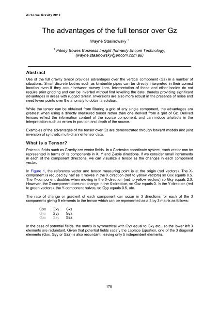
In Figure 1, the reference vector and tensor measuring point is at the origin (red vectors). The Xcomponent<br />
is reduced by half as it moves in the X direction (red to yellow vectors) so Gxx equals 0.5.<br />
The Y-component doubles when moving in the X-direction (red to yellow vectors) so Gxy equals 2.0.<br />
However, the Z-component does not change in the X-direction, so Gxz equals 0. In the Y direction (red<br />
to green vectors), the Y-component halves, so Gyy equals 0.5, etc.<br />
The rate of change or gradient of each component can occur in 3 directions for each of the 3<br />
components giving 9 elements to the tensor which can be represented as a 3 by 3 matrix as follows:<br />
Gxx Gxy Gxz<br />
Gyx Gyy Gyz<br />
Gzx Gzy Gzz<br />
In the case of potential fields, the matrix is symmetrical with Gyx equal to Gxy etc., so the lower left 3<br />
elements are redundant. Given that potential fields satisfy the Laplace Equation, one of the 3 diagonal<br />
elements (Gxx, Gyy or Gzz) is also redundant, leaving only 5 independent elements.<br />
178


