Airborne Gravity 2010 - Geoscience Australia
Airborne Gravity 2010 - Geoscience Australia
Airborne Gravity 2010 - Geoscience Australia

You also want an ePaper? Increase the reach of your titles
YUMPU automatically turns print PDFs into web optimized ePapers that Google loves.
<strong>Airborne</strong> <strong>Gravity</strong> <strong>2010</strong><br />
Acoustic coupling<br />
We put the new prototype shock mount through extensive test flights on a Cessna 208B using<br />
accelerometers to measure vibration at various locations: on the top plate, the centre steel plate, and<br />
the base plate.<br />
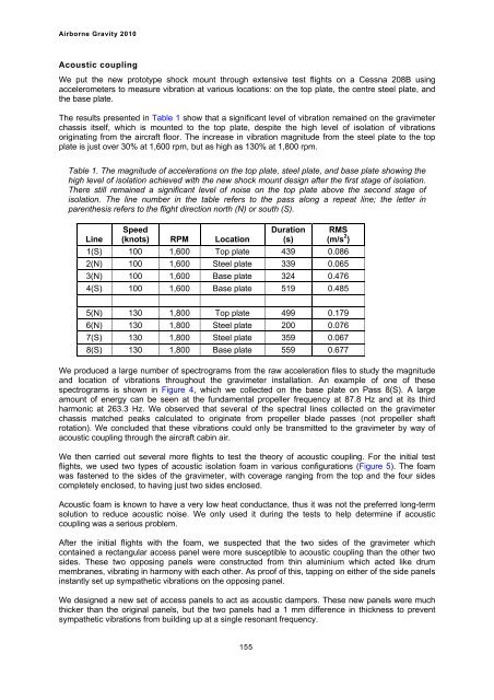
The results presented in Table 1 show that a significant level of vibration remained on the gravimeter<br />
chassis itself, which is mounted to the top plate, despite the high level of isolation of vibrations<br />
originating from the aircraft floor. The increase in vibration magnitude from the steel plate to the top<br />
plate is just over 30% at 1,600 rpm, but as high as 130% at 1,800 rpm.<br />
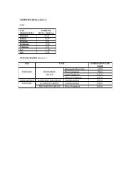
Table 1. The magnitude of accelerations on the top plate, steel plate, and base plate showing the<br />
high level of isolation achieved with the new shock mount design after the first stage of isolation.<br />
There still remained a significant level of noise on the top plate above the second stage of<br />
isolation. The line number in the table refers to the pass along a repeat line; the letter in<br />
parenthesis refers to the flight direction north (N) or south (S).<br />
Speed<br />
Duration RMS<br />
Line (knots) RPM Location (s) (m/s 2 )<br />
1(S) 100 1,600 Top plate 439 0.086<br />
2(N) 100 1,600 Steel plate 339 0.065<br />
3(N) 100 1,600 Base plate 324 0.476<br />
4(S) 100 1,600 Base plate 519 0.485<br />
5(N) 130 1,800 Top plate 499 0.179<br />
6(N) 130 1,800 Steel plate 200 0.076<br />
7(S) 130 1,800 Steel plate 359 0.067<br />
8(S) 130 1,800 Base plate 559 0.677<br />
We produced a large number of spectrograms from the raw acceleration files to study the magnitude<br />
and location of vibrations throughout the gravimeter installation. An example of one of these<br />
spectrograms is shown in Figure 4, which we collected on the base plate on Pass 8(S). A large<br />
amount of energy can be seen at the fundamental propeller frequency at 87.8 Hz and at its third<br />
harmonic at 263.3 Hz. We observed that several of the spectral lines collected on the gravimeter<br />
chassis matched peaks calculated to originate from propeller blade passes (not propeller shaft<br />
rotation). We concluded that these vibrations could only be transmitted to the gravimeter by way of<br />
acoustic coupling through the aircraft cabin air.<br />
We then carried out several more flights to test the theory of acoustic coupling. For the initial test<br />
flights, we used two types of acoustic isolation foam in various configurations (Figure 5). The foam<br />
was fastened to the sides of the gravimeter, with coverage ranging from the top and the four sides<br />
completely enclosed, to having just two sides enclosed.<br />
Acoustic foam is known to have a very low heat conductance, thus it was not the preferred long-term<br />
solution to reduce acoustic noise. We only used it during the tests to help determine if acoustic<br />
coupling was a serious problem.<br />
After the initial flights with the foam, we suspected that the two sides of the gravimeter which<br />
contained a rectangular access panel were more susceptible to acoustic coupling than the other two<br />
sides. These two opposing panels were constructed from thin aluminium which acted like drum<br />
membranes, vibrating in harmony with each other. As proof of this, tapping on either of the side panels<br />
instantly set up sympathetic vibrations on the opposing panel.<br />
We designed a new set of access panels to act as acoustic dampers. These new panels were much<br />
thicker than the original panels, but the two panels had a 1 mm difference in thickness to prevent<br />
sympathetic vibrations from building up at a single resonant frequency.<br />
155