Airborne Gravity 2010 - Geoscience Australia
Airborne Gravity 2010 - Geoscience Australia
Airborne Gravity 2010 - Geoscience Australia

Create successful ePaper yourself
Turn your PDF publications into a flip-book with our unique Google optimized e-Paper software.
<strong>Airborne</strong> <strong>Gravity</strong> <strong>2010</strong><br />
This paper describes the developments made to Air-FTG ® technology since the introductory<br />
publication (Murphy, 2004). A re-assessment and renewed understanding of full tensor gradiometry<br />
led to the development of strategies to best exploit what it offers. The improved acquisition procedures<br />
prompted development of new and improved QC, data processing and interpretational tools to<br />
facilitate an efficient workflow that could produce high quality data in a timely fashion.<br />
Full tensor gravity gradiometry<br />
Murphy (2004) describes full tensor gravity gradiometry (FTG) as a means of measuring changes in<br />
the gravity field in all directions of the field, i.e., to simultaneously measure changes and influence of<br />
changes in each of the vertical and horizontal components of the gravity field (Figure 1). This is a<br />
fundamental difference to conventional gravity in that it highlights shorter spatial wavelength aspects<br />
of the gravity field in comparison to conventional gravity meters measuring only the vertical component<br />
of the gravity field vector.<br />
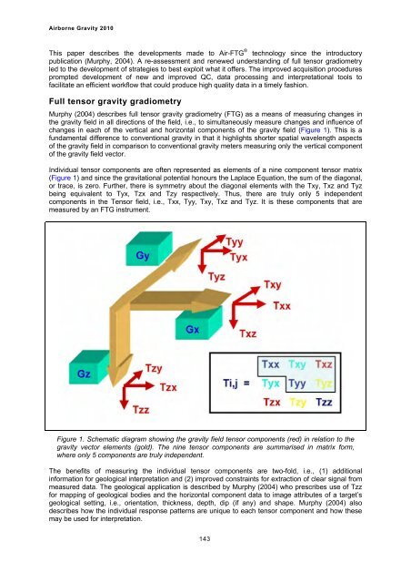
Individual tensor components are often represented as elements of a nine component tensor matrix<br />
(Figure 1) and since the gravitational potential honours the Laplace Equation, the sum of the diagonal,<br />
or trace, is zero. Further, there is symmetry about the diagonal elements with the Txy, Txz and Tyz<br />
being equivalent to Tyx, Tzx and Tzy respectively. Thus, there are truly only 5 independent<br />
components in the Tensor field, i.e., Txx, Tyy, Txy, Txz and Tyz. It is these components that are<br />
measured by an FTG instrument.<br />
Figure 1. Schematic diagram showing the gravity field tensor components (red) in relation to the<br />
gravity vector elements (gold). The nine tensor components are summarised in matrix form,<br />
where only 5 components are truly independent.<br />
The benefits of measuring the individual tensor components are two-fold, i.e., (1) additional<br />
information for geological interpretation and (2) improved constraints for extraction of clear signal from<br />
measured data. The geological application is described by Murphy (2004) who prescribes use of Tzz<br />
for mapping of geological bodies and the horizontal component data to image attributes of a target’s<br />
geological setting, i.e., orientation, thickness, depth, dip (if any) and shape. Murphy (2004) also<br />
describes how the individual response patterns are unique to each tensor component and how these<br />
may be used for interpretation.<br />
143