Airborne Gravity 2010 - Geoscience Australia
Airborne Gravity 2010 - Geoscience Australia
Airborne Gravity 2010 - Geoscience Australia

You also want an ePaper? Increase the reach of your titles
YUMPU automatically turns print PDFs into web optimized ePapers that Google loves.
<strong>Airborne</strong> <strong>Gravity</strong> <strong>2010</strong><br />
GT then undertook a detailed study of the design of the main gravimetric sensing element, or vertical<br />
accelerometer, and found that under certain conditions of induced non-orthogonal vibrations, i.e.,<br />
vibrations non-orthogonal relative to the base of the gravimeter, the accelerometer output could be<br />
offset by several tens of mGal. They concluded that the diagonal spring/damper assemblies should be<br />
removed as they could potentially induce non-orthogonal vibrations.<br />
New shock mount design<br />
In order to eliminate the problems associated with vibrations, in particular non-orthogonal vibrations,<br />
and to thus improve the performance of the gravimeter under a wider range of installations and flying<br />
conditions, we designed a totally new shock mount during the fall of 2006.<br />
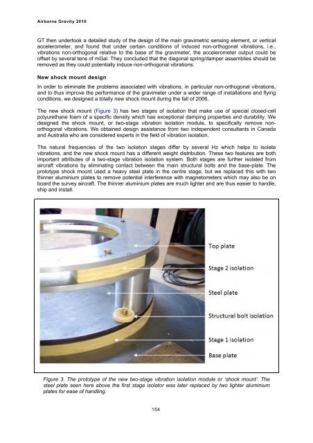
The new shock mount (Figure 3) has two stages of isolation that make use of special closed-cell<br />
polyurethane foam of a specific density which has exceptional damping properties and durability. We<br />
designed the shock mount, or two-stage vibration isolation module, to specifically remove nonorthogonal<br />
vibrations. We obtained design assistance from two independent consultants in Canada<br />
and <strong>Australia</strong> who are considered experts in the field of vibration isolation.<br />
The natural frequencies of the two isolation stages differ by several Hz which helps to isolate<br />
vibrations, and the new shock mount has a different weight distribution. These two features are both<br />
important attributes of a two-stage vibration isolation system. Both stages are further isolated from<br />
aircraft vibrations by eliminating contact between the main structural bolts and the base-plate. The<br />
prototype shock mount used a heavy steel plate in the centre stage, but we replaced this with two<br />
thinner aluminium plates to remove potential interference with magnetometers which may also be on<br />
board the survey aircraft. The thinner aluminium plates are much lighter and are thus easier to handle,<br />
ship and install.<br />
Figure 3. The prototype of the new two-stage vibration isolation module or ‘shock mount’. The<br />
steel plate seen here above the first stage isolator was later replaced by two lighter aluminium<br />
plates for ease of handling.<br />
154