- Page 1:
GEOMETRIA DE IMAGENS: DO PROJETO DO
- Page 5:
Do Rigor Na Ciência:“Naquele Imp
- Page 9:
AGRADECIMENTOSAgradeço a todos que
- Page 13:
IMAGE GEOMETRY: FROM THE SATELLITE
- Page 16 and 17:
3.1.4 HRC-CBERS 2B ................
- Page 18 and 19:
4.3 Atitude .......................
- Page 20 and 21:
FIGURA 3.18 - Desvio do posicion
- Page 22 and 23:
TABELA 3.22 - Impacto da simula
- Page 24 and 25:
TABELA 3.65 - Impacto da simula
- Page 26 and 27:
xii
- Page 28 and 29:
φ dφ gλσξ- Latitude geodésica
- Page 30 and 31:
IFOV - Instantaneous Field Of ViewI
- Page 32 and 33:
xviii
- Page 34 and 35:
Quais são os critérios para defin
- Page 36 and 37:
espaciais e sensores de varredura m
- Page 38 and 39:
(MACHADO E SILVA et al 2007), de us
- Page 41 and 42:
CAPÍTULO 2TÉCNICAS DE CORREÇÃO
- Page 43 and 44:
Nos instrumentos de varredura mecâ
- Page 45 and 46:
2.1.2 Nível 1O nível 1 realiza, b
- Page 47 and 48:
(A)Imagem(B)ImagemWS(C)WSVarreduraD
- Page 49 and 50:
As imagens no nível 2 passam por t
- Page 51 and 52:
NBarrete 1 Barrete 2Barrete 3WEFus
- Page 53 and 54:
Não faz sentido empregar o MNET di
- Page 55 and 56:
densidade desta grade deve manter c
- Page 57 and 58:
temporalmente contínuos. Por conta
- Page 59 and 60:
⎡X⎢⎢Y⎢⎣ZSatSatSat⎤⎥
- Page 61 and 62:
Como a primeira parte é idêntica
- Page 63 and 64:
2.2.3 Mapeamento Direto Nível 4O m
- Page 65 and 66:
Nós das quadriláteros homólogos(
- Page 67 and 68:
Pela abordagem adotada no mapeament
- Page 69 and 70:
Definidas as grades, identifica-se
- Page 71 and 72:
corrigido acrescido dos coeficiente
- Page 73:
De posse destas coordenadas, acessa
- Page 76 and 77:
externa e o último à geometria in
- Page 78 and 79:
O modelo de correção geométrica
- Page 80 and 81:
considerado de referência e o outr
- Page 82 and 83:
Esse conjunto de resultados permite
- Page 84 and 85:
Todos esses efeitos afetam mais a g
- Page 86 and 87:
sinθ ' sin( θ + α − dα)sin(
- Page 88 and 89:
transformação afim corrigiu a dis
- Page 90 and 91:
TABELA 3.3 - Impacto da simulação
- Page 92 and 93:
sensível ao efeito da distorção
- Page 94 and 95:
Em suma, a redução das dimensões
- Page 96 and 97:
as características do PAN, modo P
- Page 98 and 99:
TABELA 3.8 - Impacto da simulação
- Page 100 and 101:
Os níveis de degradação da dist
- Page 102 and 103:
Os dois primeiros efeitos refletem
- Page 104 and 105:
lado direito da figura 3.4 (B e C).
- Page 106 and 107:
dS = R.dα(3.17)S + dSSdα= 1 +(3.1
- Page 108 and 109:
TABELA 3.12 - Impacto da simulaçã
- Page 110 and 111:
TABELA 3.15 - Impacto da simulaçã
- Page 112 and 113:
TABELA 3.17 - Impacto da simulaçã
- Page 114 and 115:
Do mesmo modo que já havia sido ve
- Page 116 and 117:
TABELA 3.23 - Impacto da simulaçã
- Page 118 and 119:
TABELA 3.25 - Impacto da simulaçã
- Page 120 and 121:
Deve-se destacar que o satélite CB
- Page 122 and 123:
TABELA 3.31 - Impacto da simulaçã
- Page 124 and 125:
TABELA 3.33 - Impacto da simulaçã
- Page 126 and 127:
Os sensores IRMSS e IRS guardam mui
- Page 128 and 129:
TABELA 3.39 - Impacto da simulaçã
- Page 130 and 131:
TABELA 3.42 - Impacto da simulaçã
- Page 132 and 133:
TABELA 3.44 - Relação da degrada
- Page 134 and 135:
X’Órbita Descendente: Pitch (P)N
- Page 136 and 137:
vHdPLdSRRdαFIGURA 3.11 - Desvio do
- Page 138 and 139:
atitude de média nula (a média te
- Page 140 and 141:
TABELA 3.46 - Impacto da simulaçã
- Page 142 and 143:
TABELA 3.48 - Impacto da simulaçã
- Page 144 and 145:
TABELA 3.50 - Impacto da simulaçã
- Page 146 and 147:
TABELA 3.52 - Impacto da simulaçã
- Page 148 and 149:
TABELA 3.56 - Impacto da simulaçã
- Page 150 and 151:
atitude, o limiar é atingido para
- Page 152 and 153:
TABELA 3.59 - Impacto da simulaçã
- Page 154 and 155:
panorâmica. Isto explica a relaç
- Page 156 and 157:
A tabela 3.63 apresenta resultados
- Page 158 and 159:
A tabela 3.65 demonstra que o erro
- Page 160 and 161:
TABELA 3.67 - Impacto da simulaçã
- Page 162 and 163:
3.4.7 IRS-CBERS 3 e 4A influência
- Page 164 and 165: 3.4.8 AWFI-CBERS 3 e 4A influência
- Page 166 and 167: o uso de pontos de controle para re
- Page 168 and 169: Ou seja, no caso dos satélites CBE
- Page 170 and 171: e altamente presente nas bordas. Po
- Page 172 and 173: 3.8 RelevoO relevo é uma das princ
- Page 174 and 175: Deslocamento devido à altitude (m)
- Page 176 and 177: deslocamento projetado para oeste,
- Page 178 and 179: H médioFIGURA 3.20 - Efeito provoc
- Page 180 and 181: TABELA 3.75 - Avaliação da compen
- Page 182 and 183: Num s pode-se ficar surpreso com os
- Page 184 and 185: 3.8.5 PAN-CBERS 3 e 4 (modo multi-e
- Page 186 and 187: TABELA 3.81 - Avaliação do efeito
- Page 188 and 189: Em todos os casos, a adoção de um
- Page 190 and 191: As cartas topográficas trabalham c
- Page 192 and 193: Aqui se nota uma diferença na qual
- Page 194 and 195: TABELA 3.87 - Avaliação do efeito
- Page 196 and 197: TABELA 3.90 - Avaliação do efeito
- Page 198 and 199: Ainda restará o erro de registro d
- Page 200 and 201: D eslocamento devido ao erro de alt
- Page 202 and 203: TABELA 3.93 - Avaliação do efeito
- Page 204 and 205: caso das imagens Ikonos. É importa
- Page 206 and 207: TABELA 3.96 - Avaliação do uso de
- Page 208 and 209: finalmente, uma terceira com visa
- Page 210 and 211: TABELA 3.99 - Avaliação geométri
- Page 212 and 213: Para imagens em visada nadir, o ní
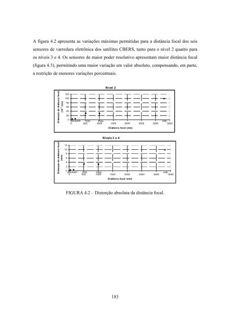
- Page 216 and 217: D istância focal ( mm)350030002500
- Page 218 and 219: Os valores máximos permitidos para
- Page 220 and 221: Nessa lista, pode-se incluir també
- Page 222 and 223: A figura 4.9 apresenta a precisão
- Page 224 and 225: FIGURA 4.10 - Precisão do MNET em
- Page 226 and 227: Essas características do aplicativ
- Page 228 and 229: qualidade geométrica das imagens,
- Page 230 and 231: 198
- Page 232 and 233: Sistema de Referência das Bandas E
- Page 234 and 235: • Eixo OZ: passa pelo centro da T
- Page 236 and 237: • Eixo OZ: aponta para o Pólo No
- Page 238 and 239: • Eixo OY: completa o triedro dir
- Page 240 and 241: Z SRDZ SRGO ElipsóideO GeoY SRDY S
- Page 242 and 243: Sistema Plano de Projeção - SPPO
- Page 244 and 245: Y L1X L10,5 1M,5dX0,5 0,51dYX ij, Y
- Page 246 and 247: Plano-Imagem Nível 3O plano-imagem
- Page 248 and 249: TABELA C.1 - Características dos s
- Page 250 and 251: TABELA C.4 - Características dos s
- Page 252 and 253: Chen, L. C.; Teo, T. A.; Rau, J. Y.
- Page 254 and 255: Machado e Silva, A. J. F. Modelo de
- Page 256: Shin, D.; Lee, T. R.; Kwak, S.; Kim


