

CMOS Optical Preamplifier Design Using Graphical Circuit Analysis
CMOS Optical Preamplifier Design Using Graphical Circuit Analysis
CMOS Optical Preamplifier Design Using Graphical Circuit Analysis

Create successful ePaper yourself
Turn your PDF publications into a flip-book with our unique Google optimized e-Paper software.
5.2 Developing an Analytic <strong>Circuit</strong> Model 117<br />
Thus, the pole frequency, ωo , of the complex-conjugate pair is given by<br />
(5.16)<br />
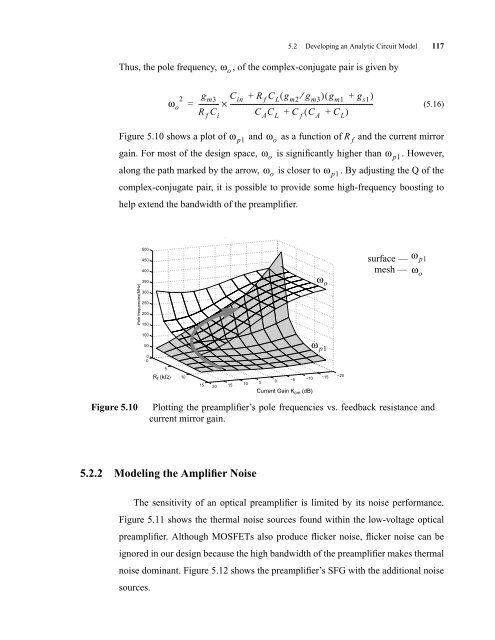
Figure 5.10 shows a plot of ω p1 and ωo as a function of R f and the current mirror<br />
gain. For most of the design space, ωo is significantly higher than ω p1 . However,<br />
along the path marked by the arrow, ωo is closer to ω p1 . By adjusting the Q of the<br />
complex-conjugate pair, it is possible to provide some high-frequency boosting to<br />
help extend the bandwidth of the preamplifier.<br />
Pole frequencies(MHz)<br />
500<br />
450<br />
400<br />
350<br />
300<br />
250<br />
200<br />
150<br />
100<br />
50<br />
0<br />
0<br />
5.2.2 Modeling the Amplifier Noise<br />
The sensitivity of an optical preamplifier is limited by its noise performance.<br />
Figure 5.11 shows the thermal noise sources found within the low-voltage optical<br />
preamplifier. Although MOSFETs also produce flicker noise, flicker noise can be<br />
ignored in our design because the high bandwidth of the preamplifier makes thermal<br />
noise dominant. Figure 5.12 shows the preamplifier’s SFG with the additional noise<br />
sources.<br />
5<br />
R f (kΩ)<br />
2<br />
ωo 10<br />
R f (kohms)<br />
gm3 ------------<br />
R f Ci Cin + R f CL( gm2 ⁄ gm3) ( gm1 + gs1) = × ----------------------------------------------------------------------------------------<br />
C AC L + C f ( C A + CL) 15<br />
1 o f<br />
20<br />
15<br />
10<br />
5<br />
0<br />
−5<br />
−10<br />
Current 20*log (Gain) Gain Kcm (dB)<br />
10<br />
Figure 5.10 Plotting the preamplifier’s pole frequencies vs. feedback resistance and<br />
current mirror gain.<br />
ω o<br />
ω p1<br />
−15<br />
−20<br />
surface —<br />
mesh —<br />
ω p1<br />
ωo


