

CMOS Optical Preamplifier Design Using Graphical Circuit Analysis
CMOS Optical Preamplifier Design Using Graphical Circuit Analysis
CMOS Optical Preamplifier Design Using Graphical Circuit Analysis

You also want an ePaper? Increase the reach of your titles
YUMPU automatically turns print PDFs into web optimized ePapers that Google loves.
2.5 An Overview of Signal-Flow Graphs 35<br />
The flow of signals in the various parts of the graph is dictated by the following<br />
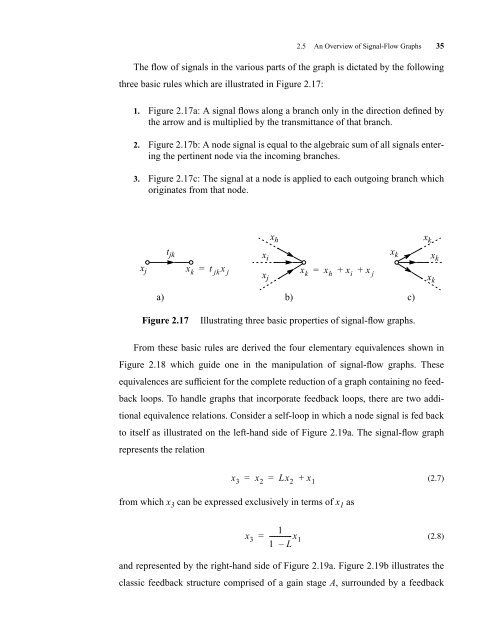
three basic rules which are illustrated in Figure 2.17:<br />
1. Figure 2.17a: A signal flows along a branch only in the direction defined by<br />
the arrow and is multiplied by the transmittance of that branch.<br />
2. Figure 2.17b: A node signal is equal to the algebraic sum of all signals entering<br />
the pertinent node via the incoming branches.<br />
3. Figure 2.17c: The signal at a node is applied to each outgoing branch which<br />
originates from that node.<br />
t jk<br />
xj xk = t jkx j<br />
Figure 2.17 Illustrating three basic properties of signal-flow graphs.<br />
From these basic rules are derived the four elementary equivalences shown in<br />
Figure 2.18 which guide one in the manipulation of signal-flow graphs. These<br />
equivalences are sufficient for the complete reduction of a graph containing no feed-<br />
back loops. To handle graphs that incorporate feedback loops, there are two addi-<br />
tional equivalence relations. Consider a self-loop in which a node signal is fed back<br />
to itself as illustrated on the left-hand side of Figure 2.19a. The signal-flow graph<br />
represents the relation<br />
from which x 3 can be expressed exclusively in terms of x 1 as<br />
x i<br />
x j<br />
x h<br />
a) b) c)<br />
x3 = x2 = Lx2 + x1 x 3<br />
1<br />
=<br />
1 – L<br />
-------------x 1<br />
xk = xh + xi + x j<br />
(2.7)<br />
(2.8)<br />
and represented by the right-hand side of Figure 2.19a. Figure 2.19b illustrates the<br />
classic feedback structure comprised of a gain stage A, surrounded by a feedback<br />
x k<br />
x k<br />
x k<br />
x k


