

CMOS Optical Preamplifier Design Using Graphical Circuit Analysis
CMOS Optical Preamplifier Design Using Graphical Circuit Analysis
CMOS Optical Preamplifier Design Using Graphical Circuit Analysis

Create successful ePaper yourself
Turn your PDF publications into a flip-book with our unique Google optimized e-Paper software.
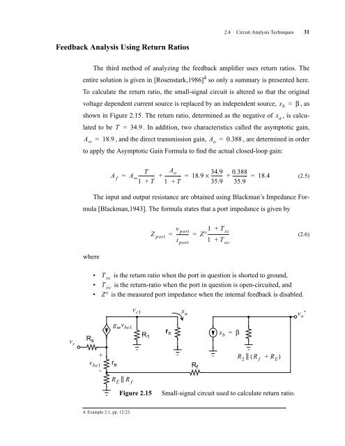
Feedback <strong>Analysis</strong> <strong>Using</strong> Return Ratios<br />
v s<br />
2.4 <strong>Circuit</strong> <strong>Analysis</strong> Techniques 31<br />
The third method of analyzing the feedback amplifier uses return ratios. The<br />
entire solution is given in [Rosenstark,1986] 4 so only a summary is presented here.<br />
To calculate the return ratio, the small-signal circuit is altered so that the original<br />
voltage dependent current source is replaced by an independent source, = β , as<br />
shown in Figure 2.15. The return ratio, determined as the negative of , is calcu-<br />
lated to be T = 34.9 . In addition, two characteristics called the asymptotic gain,<br />
A ∞<br />
= 18.9 , and the direct transmission gain, Ao = 0.388 , are determined in order<br />
to apply the Asymptotic Gain Formula to find the actual closed-loop gain:<br />
(2.5)<br />
The input and output resistance are obtained using Blackman’s Impedance For-<br />
mula [Blackman,1943]. The formula states that a port impedance is given by<br />
where<br />
R s<br />
A f<br />
• T sc is the return ratio when the port in question is shorted to ground,<br />
• T oc is the return-ratio when the port in question is open-circuited, and<br />
• Z° is the measured port impedance when the internal feedback is disabled.<br />
v be1<br />
+<br />
-<br />
r e<br />
4. Example 2.1, pp. 12-23.<br />
A o<br />
T<br />
34.9 0.388<br />
= A∞-------------- + -------------- = 18.9 × --------- + ------------ = 18.4<br />
1 + T 1 + T 35.9 35.9<br />
g m v be1<br />
R || E R f<br />
v c1<br />
R 1<br />
Z port<br />
v port<br />
---------- Z° 1 T + sc<br />
= = ------------------<br />
1 + T oc<br />
r π<br />
i port<br />
x a<br />
R f<br />
x b<br />
=<br />
β<br />
x a<br />
R || 2 ( R f + RE) Figure 2.15 Small-signal circuit used to calculate return ratio.<br />
x b<br />
(2.6)<br />
v o ′


