

CMOS Optical Preamplifier Design Using Graphical Circuit Analysis
CMOS Optical Preamplifier Design Using Graphical Circuit Analysis
CMOS Optical Preamplifier Design Using Graphical Circuit Analysis

Create successful ePaper yourself
Turn your PDF publications into a flip-book with our unique Google optimized e-Paper software.
4.2 <strong>Circuit</strong> <strong>Analysis</strong> <strong>Using</strong> Driving-Point Impedances 81<br />
EXAMPLE 4.1, we find that the driving-point impedance for both nodes is zero<br />
since the nodes are shorted to ground by the voltage sources. For the same reason,<br />
the short-circuit currents of both nodes are infinite. Thus,<br />
and we have no answer.<br />
V 1<br />
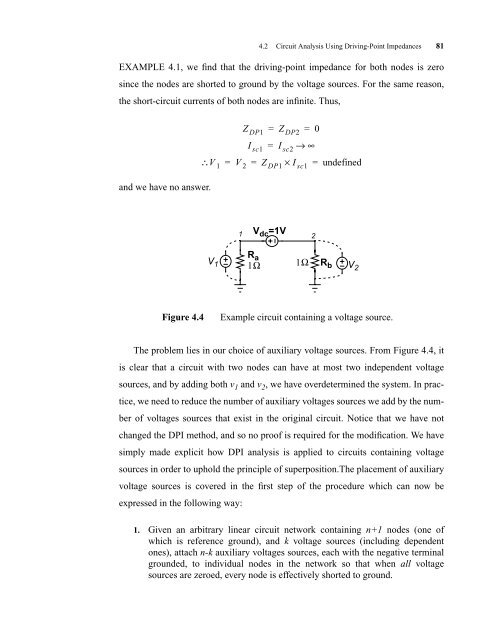
The problem lies in our choice of auxiliary voltage sources. From Figure 4.4, it<br />
is clear that a circuit with two nodes can have at most two independent voltage<br />
sources, and by adding both v 1 and v 2 , we have overdetermined the system. In prac-<br />
tice, we need to reduce the number of auxiliary voltages sources we add by the num-<br />
ber of voltages sources that exist in the original circuit. Notice that we have not<br />
changed the DPI method, and so no proof is required for the modification. We have<br />
simply made explicit how DPI analysis is applied to circuits containing voltage<br />
sources in order to uphold the principle of superposition.The placement of auxiliary<br />
voltage sources is covered in the first step of the procedure which can now be<br />
expressed in the following way:<br />
Z DP1 = Z DP2 = 0<br />
I sc1 = I sc2 → ∞<br />
∴ = V 2 = Z DP1 × I sc1 = undefined<br />
V dc =1V<br />
1 2<br />
R a<br />
V 1 1Ω 1Ω<br />
1. Given an arbitrary linear circuit network containing n+1 nodes (one of<br />
which is reference ground), and k voltage sources (including dependent<br />
ones), attach n-k auxiliary voltages sources, each with the negative terminal<br />
grounded, to individual nodes in the network so that when all voltage<br />
sources are zeroed, every node is effectively shorted to ground.<br />
R b<br />
Figure 4.4 Example circuit containing a voltage source.<br />
V 2


