

CMOS Optical Preamplifier Design Using Graphical Circuit Analysis
CMOS Optical Preamplifier Design Using Graphical Circuit Analysis
CMOS Optical Preamplifier Design Using Graphical Circuit Analysis

Create successful ePaper yourself
Turn your PDF publications into a flip-book with our unique Google optimized e-Paper software.
2.3 Transimpedance Amplifier <strong>Design</strong> Requirements 16<br />
2.3 TRANSIMPEDANCE AMPLIFIER DESIGN REQUIREMENTS<br />
Traditionally, the design challenge of fiber-optic preamplifiers has been in opti-<br />
mizing the trade-offs between sensitivity, speed, and transimpedance gain. As dis-<br />
cussed in the previous chapter, new applications of optical communications have<br />
introduced additional receiver requirements such as wide dynamic range, ambient<br />
light rejection, and low-voltage operation. This section discusses each of these<br />
requirements in greater detail, and reviews previously reported solutions.<br />
2.3.1 Wide Dynamic Range<br />
C T<br />
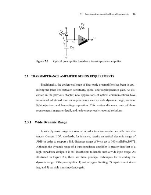
Figure 2.6 <strong>Optical</strong> preamplifier based on a transimpedance amplifier.<br />
R f<br />
A wide dynamic range is essential in order to accommodate variable link dis-<br />
tances. Current IrDA standards, for instance, require an optical dynamic range of<br />
51dB in order to support a link distances range of 0 cm up to 100 cm[IrDA,1997].<br />
Although the dynamic range of a transimpedance amplifier is greater than that of a<br />
high-impedance design, it is still insufficient to handle such a wide input range. As<br />
illustrated in Figure 2.7, there are three principal techniques for extending the<br />
dynamic range of the preamplifier: 1) output signal limiting, 2) input current steer-<br />
ing, and 3) variable transimpedance gain.<br />
i s<br />
v s<br />
-A<br />
v out


