

CMOS Optical Preamplifier Design Using Graphical Circuit Analysis
CMOS Optical Preamplifier Design Using Graphical Circuit Analysis
CMOS Optical Preamplifier Design Using Graphical Circuit Analysis

Create successful ePaper yourself
Turn your PDF publications into a flip-book with our unique Google optimized e-Paper software.
Source<br />
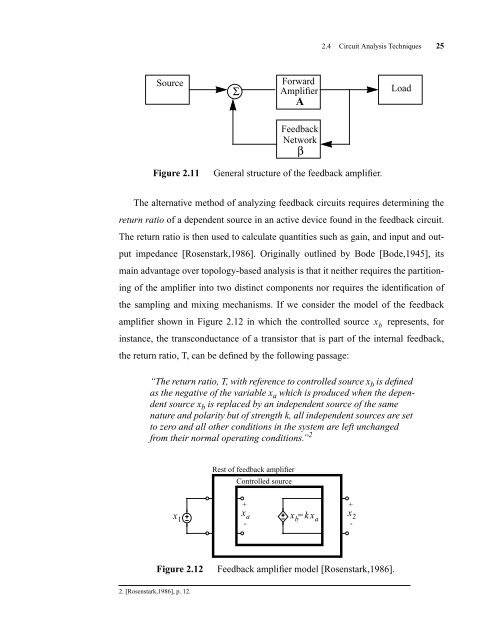
Figure 2.11 General structure of the feedback amplifier.<br />
2.4 <strong>Circuit</strong> <strong>Analysis</strong> Techniques 25<br />
The alternative method of analyzing feedback circuits requires determining the<br />
return ratio of a dependent source in an active device found in the feedback circuit.<br />
The return ratio is then used to calculate quantities such as gain, and input and out-<br />
put impedance [Rosenstark,1986]. Originally outlined by Bode [Bode,1945], its<br />
main advantage over topology-based analysis is that it neither requires the partition-<br />
ing of the amplifier into two distinct components nor requires the identification of<br />
the sampling and mixing mechanisms. If we consider the model of the feedback<br />
amplifier shown in Figure 2.12 in which the controlled source represents, for<br />
instance, the transconductance of a transistor that is part of the internal feedback,<br />
the return ratio, T, can be defined by the following passage:<br />
“The return ratio,T,with reference to controlled source x b is defined<br />
as the negative of the variable x a which is produced when the dependent<br />
source x b is replaced by an independent source of the same<br />
nature and polarity but of strength k,all independent sources are set<br />
to zero and all other conditions in the system are left unchanged<br />
from their normal operating conditions.” 2<br />
x 1<br />
2. [Rosenstark,1986], p. 12.<br />
Σ<br />
Rest of feedback amplifier<br />
Controlled source<br />
+<br />
xa -<br />
Forward<br />
Amplifier<br />
A<br />
Feedback<br />
Network<br />
β<br />
xb= kxa Figure 2.12 Feedback amplifier model [Rosenstark,1986].<br />
+<br />
x2 -<br />
x b<br />
Load


