

CMOS Optical Preamplifier Design Using Graphical Circuit Analysis
CMOS Optical Preamplifier Design Using Graphical Circuit Analysis
CMOS Optical Preamplifier Design Using Graphical Circuit Analysis

Create successful ePaper yourself
Turn your PDF publications into a flip-book with our unique Google optimized e-Paper software.
v 2<br />
4.3 DPI/SFG: Combining DPI <strong>Analysis</strong> and Signal-Flow Graphs 86<br />
4 S<br />
1 S<br />
2 S<br />
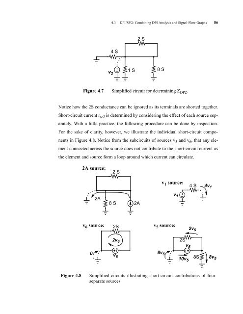
Notice how the 2S conductance can be ignored as its terminals are shorted together.<br />
Short-circuit current i sc2 is determined by considering the effect of each source sep-<br />
arately. With a little practice, the following procedure can be done by inspection.<br />
For the sake of clarity, however, we illustrate the individual short-circuit compo-<br />
nents in Figure 4.8. Notice from the subcircuits of sources v 5 and v 6 , that any ele-<br />
ment connected across the source does not contribute to the short-circuit current as<br />
8 S<br />
Figure 4.7 Simplified circuit for determining Z DP2 .<br />
the element and source form a loop around which current can circulate.<br />
2A source:<br />
2A<br />
2 S<br />
8 S<br />
2A<br />
v6 source: 2S<br />
v5 source:<br />
0<br />
2v 6<br />
v 6<br />
Figure 4.8 Simplified circuits illustrating short-circuit contributions of four<br />
separate sources.<br />
8v 5<br />
v 1 source:<br />
v 1<br />
2S<br />
v 5<br />
10v 5<br />
4 S 4v 1<br />
2v 5<br />
8S<br />
8v 5


