

CMOS Optical Preamplifier Design Using Graphical Circuit Analysis
CMOS Optical Preamplifier Design Using Graphical Circuit Analysis
CMOS Optical Preamplifier Design Using Graphical Circuit Analysis

You also want an ePaper? Increase the reach of your titles
YUMPU automatically turns print PDFs into web optimized ePapers that Google loves.
Transimpedance (dBΩ)<br />
90<br />
80<br />
60<br />
40<br />
20<br />
5nA<br />
50nA<br />
500nA<br />
5µA<br />
3.2 A Feedback Topology for Ambient Light Rejection 55<br />
0<br />
100Hz 10kHz 1MHz<br />
100MHz 10 GHz<br />
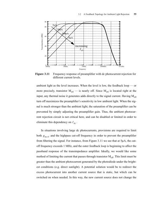
Figure 3.11 Frequency response of preamplifier with dc photocurrent rejection for<br />
different current levels.<br />
ambient light as the level increases. When the level is low, the feedback loop — or<br />
more precisely, transistor M ctl — is nearly off. Since M ctl is located right at the<br />
input, any thermal noise it generates adds directly to the signal current. Having Mctl turn off maximizes the preamplifier’s sensitivity in low ambient light. When the sig-<br />
nal is much stronger than the ambient light, the saturation of the preamplifier can be<br />
prevented by simply adjusting the preamplifier gain. Thus, the ambient photocur-<br />
rent rejection circuit is not critical here, and can be disabled or limited in order to<br />
eliminate this dependency on .<br />
In situations involving large dc photocurrents, provisions are required to limit<br />
both and the highpass cut-off frequency in order to prevent the preamplifier<br />
g mctl<br />
I dc<br />
increasing<br />
I dc<br />
frequency<br />
from filtering the signal. For instance, from Figure 3.11 we see that at 5µA, the cut-<br />
off frequency exceeds 1 MHz, and the outer feedback loop is beginning to affect the<br />
passband response of the transimpedance amplifier. Ideally, we would like some<br />
method of limiting the current that passes through transistor M ctl . This limit must be<br />
greater than the ambient photocurrent generated by the photodiode under the bright-<br />
est conditions (e.g. direct sunlight). A potential solution would be to redirect the<br />
excess photocurrent into another current source that is static, but which can be<br />
switched on when needed. In this way, the new current source does not change the


