

CMOS Optical Preamplifier Design Using Graphical Circuit Analysis
CMOS Optical Preamplifier Design Using Graphical Circuit Analysis
CMOS Optical Preamplifier Design Using Graphical Circuit Analysis

You also want an ePaper? Increase the reach of your titles
YUMPU automatically turns print PDFs into web optimized ePapers that Google loves.
5.2 Developing an Analytic <strong>Circuit</strong> Model 124<br />
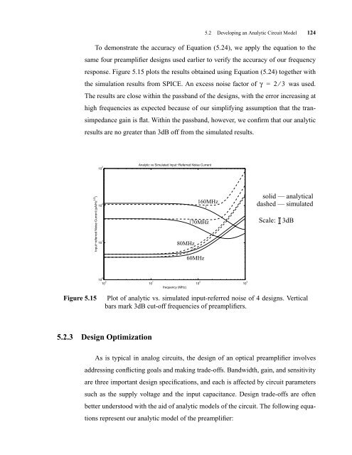
To demonstrate the accuracy of Equation (5.24), we apply the equation to the<br />
same four preamplifier designs used earlier to verify the accuracy of our frequency<br />
response. Figure 5.15 plots the results obtained using Equation (5.24) together with<br />
the simulation results from SPICE. An excess noise factor of γ = 2 ⁄ 3 was used.<br />
The results are close within the passband of the designs, with the error increasing at<br />
high frequencies as expected because of our simplifying assumption that the tran-<br />
simpedance gain is flat. Within the passband, however, we confirm that our analytic<br />
results are no greater than 3dB off from the simulated results.<br />
Input−referred Noise Current (pA/Hz 1/2 )<br />
10 3<br />
10 2<br />
10 1<br />
10 0<br />
10 0<br />
5.2.3 <strong>Design</strong> Optimization<br />
Analytic vs Simulated Input−Referred Noise Current<br />
10 1<br />
80MHz<br />
frequency (MHz)<br />
70MHz<br />
60MHz<br />
160MHz<br />
Figure 5.15 Plot of analytic vs. simulated input-referred noise of 4 designs. Vertical<br />
bars mark 3dB cut-off frequencies of preamplifiers.<br />
As is typical in analog circuits, the design of an optical preamplifier involves<br />
addressing conflicting goals and making trade-offs. Bandwidth, gain, and sensitivity<br />
are three important design specifications, and each is affected by circuit parameters<br />
such as the supply voltage and the input capacitance. <strong>Design</strong> trade-offs are often<br />
better understood with the aid of analytic models of the circuit. The following equa-<br />
tions represent our analytic model of the preamplifier:<br />
10 2<br />
10 3<br />
solid — analytical<br />
dashed — simulated<br />
Scale:<br />
3dB


